Comprehensive Guide to CNC Milling Operations
Mastering these core operations is essential for achieving precision results in modern manufacturing.
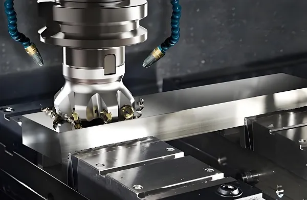
1. Face Milling: Creating Precision Datum Surfaces
Face milling is the foundational machining process for creating large, flat reference surfaces with exceptional accuracy. It employs a disc-shaped face mill with multiple cutting inserts to remove material across the workpiece surface. The primary objectives are to achieve precise flatness (often ≤0.01mm per 100mm span) and a controlled surface finish (typically Ra 1.6μm or better), which serve as the datum for all subsequent machining operations.
Technical Insight: Achieving Mirror Finishes
For optical or sealing applications, we employ wiper inserts and high-precision spindles to achieve surface roughness values as low as Ra 0.4μm. This eliminates the need for secondary polishing operations, saving time and cost.
Ideal for: Creating mounting surfaces, sealing faces, optical platforms, and preparing stock for further precision machining.
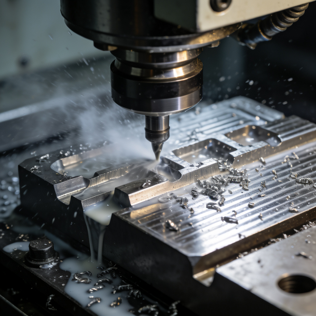
Face milling produces ultra-flat reference surfaces, essential for part alignment and assembly.
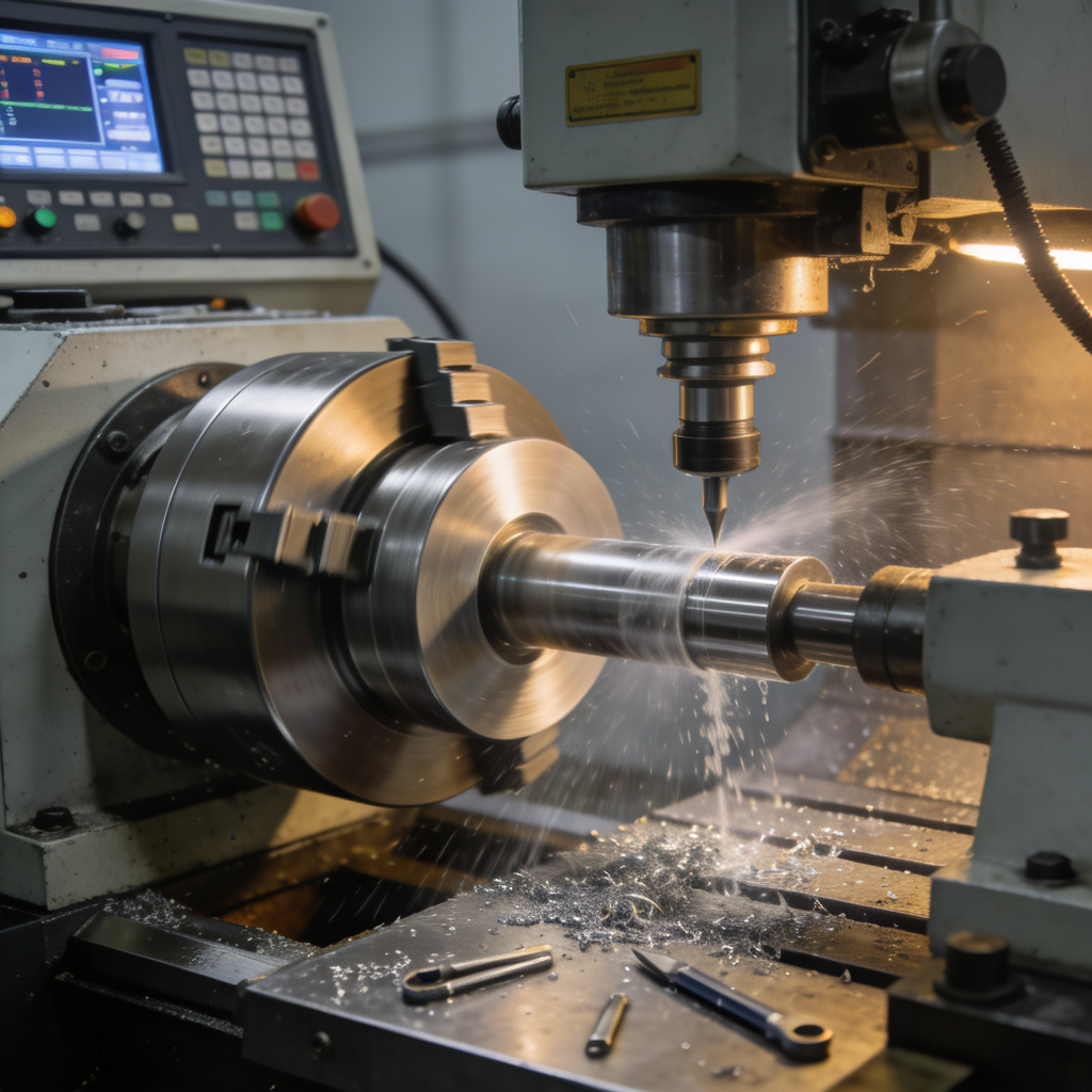
End milling creates precise slots, keyways, and pockets for functional part features.
2. End Milling: Machining Slots, Pockets, and Step Features
End milling is a versatile operation using a cylindrical cutter with cutting edges on both its end and periphery. It is the primary method for machining open slots, closed pockets (with entry holes), step downs, and profiles. The cutter’s diameter, flute count, and length are carefully selected based on feature geometry, material, and depth-to-width ratio.
Technical Insight: Trochoidal Milling for Deep Pockets
For deep pockets, we utilize trochoidal (adaptive) toolpaths that maintain constant tool load, dramatically reducing heat, vibration, and tool wear compared to conventional linear paths.
Ideal for: Creating keyways for shafts, cooling channels in molds, mounting slots in brackets, and intricate internal features.
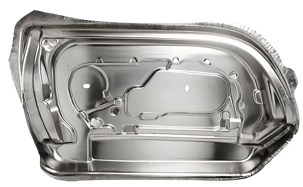
3. 5-Axis Machining: Complex Geometry Solutions
Our state-of-the-art 5-axis CNC machining centers enable the production of highly complex parts with intricate geometries that would be impossible to manufacture using traditional 3-axis machines. This technology allows the cutting tool to approach the workpiece from any angle, enabling the machining of undercuts, compound angles, and complex 3D surfaces in a single setup.
Technical Insight: Simultaneous 5-Axis Machining
Simultaneous 5-axis machining allows all axes to move at the same time, creating smooth, continuous toolpaths that eliminate visible step lines and reduce cycle times by up to 60% compared to traditional indexing methods.
Ideal for: Aerospace components, medical implants, turbine blades, and any part requiring complex, organic 3D geometry.
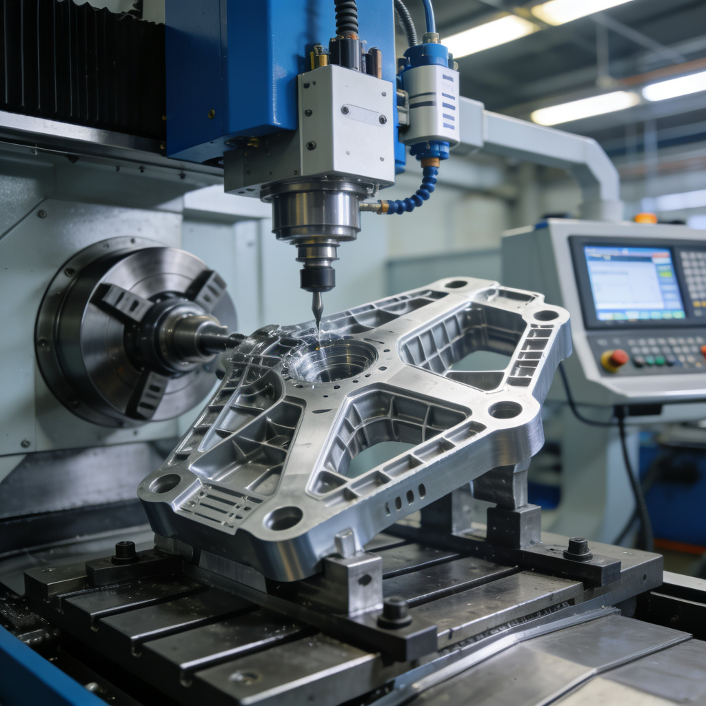
5-axis machining enables the creation of complex geometries with exceptional precision and efficiency.
Advanced Material & Technology Capabilities
Machining Over 200 Engineering Materials
Our expertise spans a vast range of materials, each requiring specific tooling, parameters, and techniques. We don’t just cut metal; we understand its behavior under the tool.
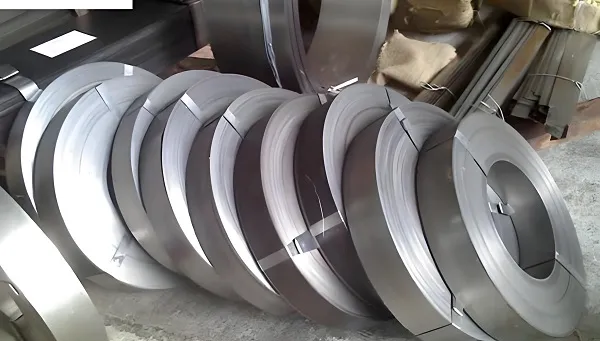
- Metals: Aluminum Alloys, Stainless Steels, Tool Steels, Titanium, Brass, Copper, Exotic Alloys.
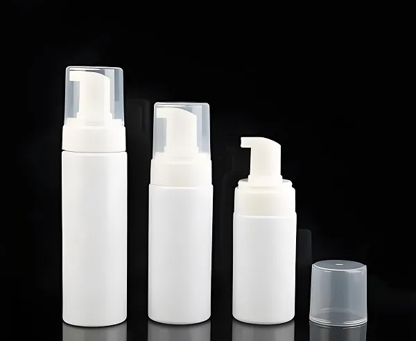
- Plastics & Composites: PEEK, Delrin, Nylon, PTFE, Polycarbonate, Carbon Fiber.
For instance, machining PEEK for medical implants requires sharp tools, high speeds, and excellent cooling to prevent melting and achieve the required biocompatible surface finish.
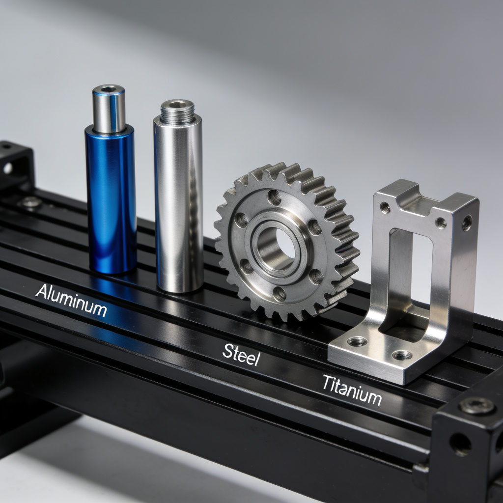
A sample of parts machined from various metals and plastics, showcasing material versatility.
Quality Control & Certification
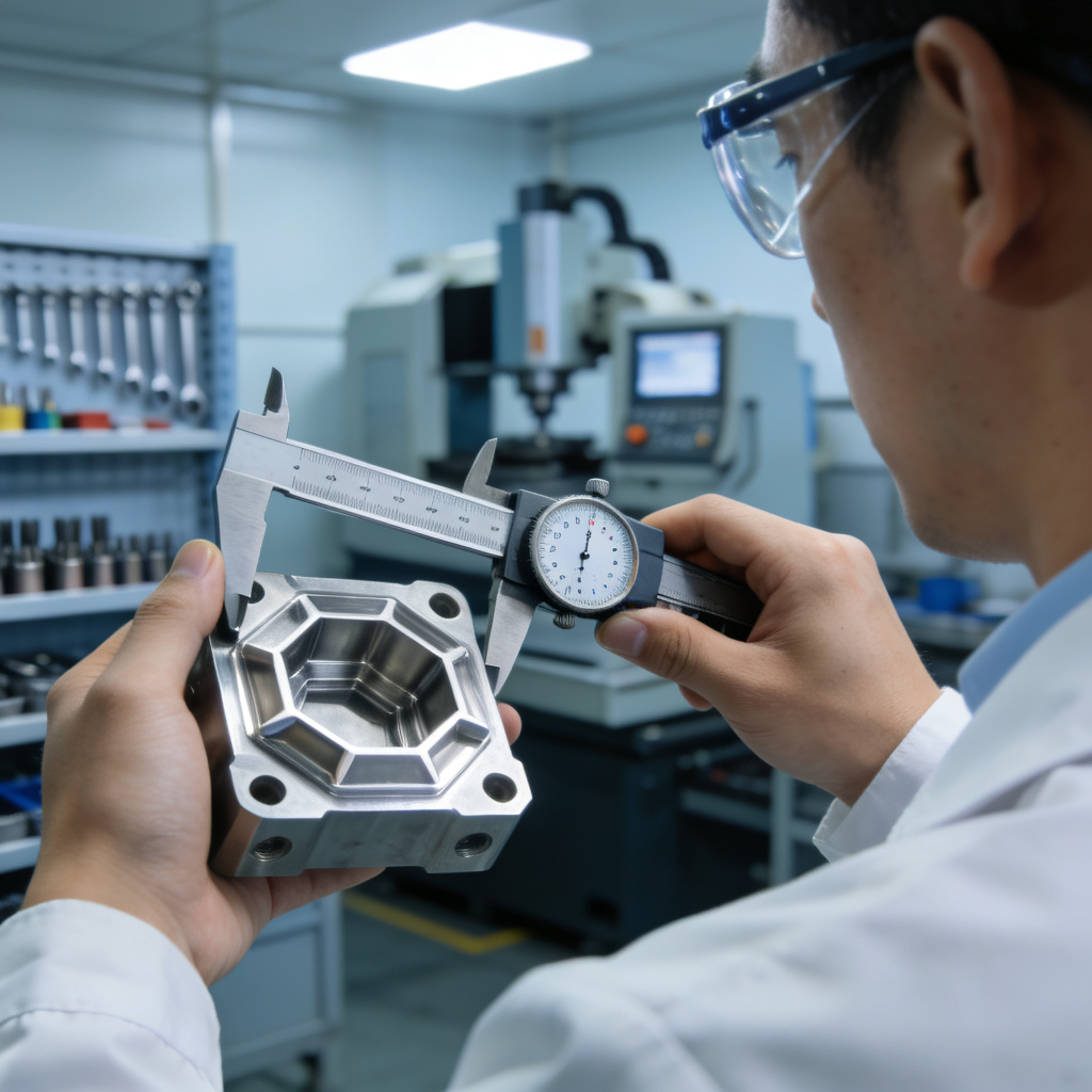
Our quality control technicians use state-of-the-art measuring equipment to ensure every part meets specifications.
ISO 9001:2015 Certified Quality Management
We maintain a strict quality management system certified to ISO 9001:2015 standards. Our quality control processes include:
- First Article Inspection (FAI): Complete dimensional verification of the first production part
- In-Process Inspection: Regular checks during production to maintain quality
- Final Inspection: Comprehensive quality check before shipment
- Coordinate Measuring Machine (CMM): High-precision 3D measurement of complex geometries
- Surface Finish Analysis: Verification of surface roughness parameters
We provide detailed inspection reports with every shipment, ensuring complete traceability and quality assurance.
Customer Success Stories
Aerospace Component Manufacturing
“Goldcattle delivered 500 complex aerospace components with tight tolerances of ±0.01mm. Their 5-axis machining capabilities allowed us to reduce our supply chain by eliminating secondary operations.”
— John Smith, Manufacturing Director, Aerospace Systems Inc.
Medical Device Prototyping
“The precision and quality of the medical device prototypes exceeded our expectations. Goldcattle’s expertise with biocompatible materials was crucial for our regulatory approval process.”
— Sarah Johnson, R&D Manager, Medical Innovations Ltd.
Automotive Tooling Production
“Goldcattle’s ability to machine hardened tool steels with complex geometries helped us reduce our tooling lead time by 40%. Their on-time delivery performance is exceptional.”
— Michael Chen, Tooling Engineer, Automotive Manufacturing Corp.
Frequently Asked Questions
What is the minimum order quantity?
We accept orders of all sizes, from single prototypes to high-volume production runs. Our flexible manufacturing capabilities allow us to accommodate both small and large orders efficiently.
What file formats do you accept for CAD designs?
We accept all common CAD file formats including STEP, IGES, SLDPRT, X_T, Parasolid, DWG, and PDF. We can also work with image files and hand-drawn sketches for simple parts.
How long does it take to get a quote?
We typically provide detailed quotes within 24-48 hours of receiving your design files. For complex projects, we may need additional time to perform a thorough DFM analysis.
What is your typical lead time?
Lead times vary depending on the complexity of the part and order quantity. Prototypes can typically be delivered within 3-5 business days, while production runs may take 1-4 weeks.
Do you offer surface finishing services?
Yes, we offer a comprehensive range of surface finishing services including anodizing, plating, painting, powder coating, and polishing. We can also provide passivation, heat treatment, and other specialized treatments.
Ready to Start Your Precision Project?
Upload your design files today. You’ll receive a detailed quote and actionable DFM feedback from our engineering team within 24 hours—no obligation.