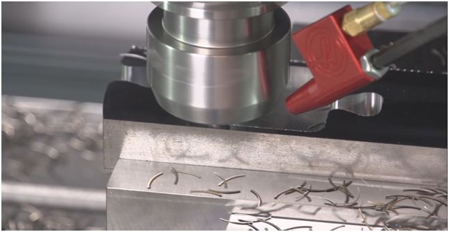
In modern CNC machining workshops, tool vibration marks are a frustrating issue for technicians. These seemingly minor surface defects not only affect product appearance quality but can also lead to reduced assembly precision, sealing failures, and even safety hazards. This article will explore the causes, impacts, and systematic solutions for tool vibration marks in CNC machining, helping readers fully understand and effectively solve this technical challenge.
I. Understanding Tool Vibration Marks: More Than Just a “Surface Issue”
1.1 What Are Tool Vibration Marks?
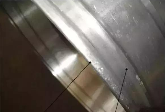
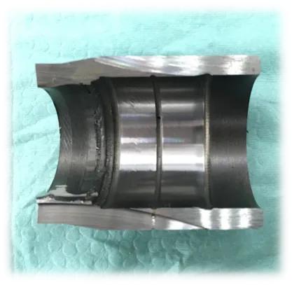
Tool vibration marks, also known as chatter marks, vibration lines, or ripples, refer to periodic stripes or wavy patterns formed on the workpiece surface due to abnormal vibrations between the cutting tool and workpiece during CNC machining. These marks typically exhibit regular spacing and patterns, directly reflecting the vibration frequency during the machining process.
1.2 The Hazards of Tool Vibration Marks
The dangers of tool vibration marks extend far beyond just appearance issues:
- Reduced machining precision: Increased surface roughness and difficulty controlling dimensional accuracy
- Shorter tool life: Continuous vibration accelerates tool wear and increases tool change frequency
- Decreased machining efficiency: Frequent parameter adjustments and potential rework
- Higher workpiece rejection rate: Severe cases may render entire workpieces scrap
- Equipment damage risk: Long-term vibration may damage machine spindles and guideways
II. Formation Mechanism of Vibration Marks: The “Chain Reaction” of Vibration
2.1 Basic Vibration Principles
Tool vibration in CNC machining is essentially a phenomenon of self-excited vibration or forced vibration. When the vibration frequency generated during cutting approaches the natural frequency of the system, resonance occurs, causing a dramatic increase in vibration amplitude and leaving obvious marks on the workpiece surface.
2.2 Main Characteristics of Vibration Marks
- Periodicity: Uniform spacing related to vibration frequency
- Directionality: Usually along the tool feed direction or spindle rotation direction
- Consistency: Repeats under the same machining conditions
- Identifiability: Easily detected through visual inspection or touch
III. The Five Root Causes of Vibration Marks
3.1 Tool System Issues
Insufficient tool rigidity is the primary cause of vibration marks:
- Excessive tool overhang: Longer projection length reduces rigidity and increases vibration susceptibility
- Small tool diameter: Slender tool shanks easily bend and deform under cutting forces
- Inappropriate tool material: Hardness or toughness not matching current cutting conditions
- Severe tool wear: Dull cutting edges increase cutting forces and instability
- Insecure tool clamping: Significant runout in tool holders affects machining stability
3.2 Workpiece and Fixture Factors
Insufficient workpiece clamping rigidity is another important factor:
- Excessive workpiece overhang: Cantilever structures easily generate vibrations
- Poor fixture rigidity: Inability to provide sufficient support force
- Insufficient clamping force: Workpiece displacement under cutting forces
- Poor workpiece rigidity: Thin-walled parts, slender components, and other easily deformable workpieces
- Unreasonable clamping methods: Single-point clamping or insufficient support points
3.3 Inappropriate Cutting Parameters
Incorrect machining parameter selection is the most common cause:
- Inappropriate cutting speed: Both excessively high and low speeds can trigger vibrations
- Excessive feed rate: Increases cutting forces beyond system capacity
- Excessive depth of cut: Causes sharp increases in cutting forces
- Poor parameter combination: Improper matching of speed, feed, and depth of cut
3.4 Machine Performance Issues
Equipment rigidity and precision directly affect machining stability:
- Insufficient machine rigidity: Inadequate rigidity in bed, column, and other structures
- Spindle system problems: Worn spindle bearings, excessive clearance
- Guideway wear: Reduced guideway precision affecting smooth movement
- Ball screw backlash: Transmission system clearance causing reverse impact
- Machine installation issues: Improper level adjustment or unstable foundation
3.5 Material and Environmental Factors
Workpiece material properties and machining environment also affect vibration:
- Uneven material hardness: Large fluctuations in cutting resistance
- Excessive material toughness: Increases cutting difficulty and vibration
- Environmental vibration interference: Vibration from surrounding equipment transmitted to the machine
- Temperature changes: Affects machine precision and material properties
IV. Systematic Solutions: Eliminating Vibration Marks at the Source
4.1 Tool System Optimization
Improving tool rigidity is key:
- Shorten tool projection length
-
- Follow the “5× diameter rule”: Tool projection should not exceed 5 times its diameter
-
- Use short tool holders and short-flute tools
-
- For deep cavity machining, use custom short-flute tools
- Select high-rigidity tools
-
- Choose tools with large diameters and thick shanks
-
- Select high-performance tool materials such as carbide
-
- Use tools with unequal pitch or sparse teeth to reduce resonance
- Optimize tool geometry parameters
-
- Select appropriate rake angle, clearance angle, and cutting edge angle
-
- Reduce nose radius to lower cutting resistance
-
- Use sharp cutting edges
- Improve tool clamping methods
-
- Use high-precision tool holders (e.g., thermal shrink, hydraulic)
-
- Ensure secure tool installation with minimal runout
-
- Regularly inspect tool holders and tools for wear
4.2 Workpiece Clamping Improvements
Enhance workpiece rigidity and stability:
- Optimize fixture design
-
- Use high-rigidity fixtures
-
- Increase clamping and support points
-
- Ensure workpiece center of gravity is close to the spindle
- Improve clamping methods
-
- Use multi-point clamping to avoid single-point loading
-
- Use auxiliary supports (steady rests, follow rests)
-
- For thin-walled parts, use specialized fixtures and supports
- Control clamping force
-
- Ensure sufficient clamping force to prevent workpiece movement
-
- Avoid excessive clamping that causes workpiece deformation
-
- Use adjustable clamping devices
4.3 Cutting Parameter Optimization
Reasonable parameter settings are fundamental:
- Adjust cutting speed
-
- Avoid the natural frequency range of the system
-
- Find the optimal speed range through test cuts
-
- For aluminum alloys, generally select higher cutting speeds
- Optimize feed rate
-
- Set reasonably based on tool and workpiece conditions
-
- Appropriately reduce feed for vibration-prone situations
-
- Use variable feed strategies, reducing speed at corners
- Control depth of cut
-
- Use layered cutting with smaller depths per pass
-
- Use smaller depths for difficult-to-machine materials
-
- Use smaller depths at internal corners
- Parameter combination optimization
-
- Use “high speed, small depth, medium feed” combinations
-
- Employ dynamic milling techniques to maintain constant cutting forces
-
- Use CAM software for parameter optimization
4.4 Machine Maintenance and Improvement
Ensure equipment is in optimal condition:
- Regular maintenance
-
- Check spindle bearing clearance and replace worn components in a timely manner
-
- Maintain guideways and ball screws, ensuring proper lubrication
-
- Regularly calibrate machine precision
- Improve machine rigidity
-
- Consider structural reinforcement for older equipment
-
- Ensure proper machine level adjustment
-
- Improve machine installation foundation
- Use vibration damping technology
-
- Install vibration damping devices or damping materials
-
- Use active vibration damping systems
-
- Implement isolation measures to reduce environmental interference
4.5 Advanced Machining Technology Applications
Utilize modern technology to enhance machining stability:
- Dynamic milling technology
-
- Use circular interpolation to maintain constant cutting forces
-
- Machine large areas with small diameter tools
-
- Reduce tool-workpiece contact area
- Vibration monitoring and control
-
- Install vibration sensors for real-time monitoring
-
- Use adaptive control systems for automatic parameter adjustment
-
- Utilize AI technology for vibration prediction and prevention
- Simulation technology application
-
- Use machining simulation software to predict vibration risks
-
- Optimize machining parameters in a virtual environment
-
- Perform tool path verification and optimization
V. Practical Case Studies: From Failure to Success
5.1 Case 1: Aluminum Alloy Housing Slope Machining
Problem description: Severe vibration marks appeared during slope machining of an aluminum alloy housing for a facial recognition module.
Solutions:
- Switch to formed diamond tools to improve machining precision
- Reduce feed rate to increase machining stability
- Use polishing and grinding processes to repair vibration marks
Results: Significant reduction in vibration marks and substantial improvement in surface quality.
5.2 Case 2: Deep Hole Machining Vibration Problem
Problem description: Continuous vibration occurred during deep hole machining, affecting hole wall quality.
Solutions:
- Use vibration-damping tool holders and short-flute tools
- Optimize cutting parameters and reduce feed rate
- Adopt step-by-step machining strategy
Results: Vibration phenomenon basically eliminated, and hole wall finish met requirements.
5.3 Case 3: Thin-Walled Part Machining Vibration
Problem description: Thin-walled aluminum parts were prone to deformation and vibration during machining.
Solutions:
- Design specialized fixtures with increased support points
- Use small depth of cut and high feed machining strategy
- Employ high-speed machining technology
Results: Machining stability significantly improved, and part deformation controlled within allowable limits.
VI. Preventive Measures and Best Practices
6.1 Pre-Machining Prevention
Identify and avoid vibration risks in advance:
- Process planning stage
-
- Reasonably design part structures, avoiding overly weak areas
-
- Select appropriate machining sequences, starting with rigid areas
-
- Develop detailed machining plans and parameter schedules
- Equipment inspection
-
- Check machine condition and precision before machining
-
- Inspect tool wear and tool holder precision
-
- Verify fixture rigidity and reliability
6.2 In-Process Monitoring
Real-time monitoring and adjustment:
- Auditory monitoring
-
- Pay attention to abnormal sounds during machining
-
- Adjust parameters promptly when chatter is heard
-
- Familiarize with the difference between normal and abnormal machining sounds
- Visual observation
-
- Regularly check machining surface quality
-
- Observe chip shape and condition
-
- Monitor tool and workpiece vibration
- Parameter adjustment
-
- Adjust parameters in real-time based on machining conditions
-
- Appropriately reduce speed in vibration-prone areas (e.g., corners)
-
- Establish standard procedures for parameter adjustment
6.3 Continuous Improvement
Constantly optimize machining processes:
- Experience summary
-
- Record successful parameter combinations
-
- Establish machining parameter libraries for common materials
-
- Summarize solutions to vibration problems
- Technology upgrades
-
- Stay informed about new technologies and equipment developments
-
- Provide regular training for operators
-
- Introduce advanced machining technologies and tools
VII. Conclusion: The “Nemesis” of Vibration Marks Is in Your Hands
Although tool vibration marks are a common problem in CNC machining, they are not unsolvable. By deeply understanding the causes of vibration, adopting systematic solutions, and optimizing from multiple aspects including tools, fixtures, parameters, and equipment, we can effectively control or even eliminate vibration marks.
The key lies in comprehensive analysis, systematic solutions, and continuous improvement. Every occurrence of vibration marks is an opportunity for technical improvement. By continuously accumulating experience and optimizing processes, we can not only solve current problems but also enhance overall machining capabilities and product quality.
In the era of intelligent manufacturing, vibration mark control will become more intelligent and automated. However, regardless of technological advancements, solid foundational knowledge, rich practical experience, and rigorous work attitudes remain the fundamental guarantees for solving technical challenges. Let’s work together to overcome this “persistent ailment” of vibration marks and contribute to the high-quality development of manufacturing!