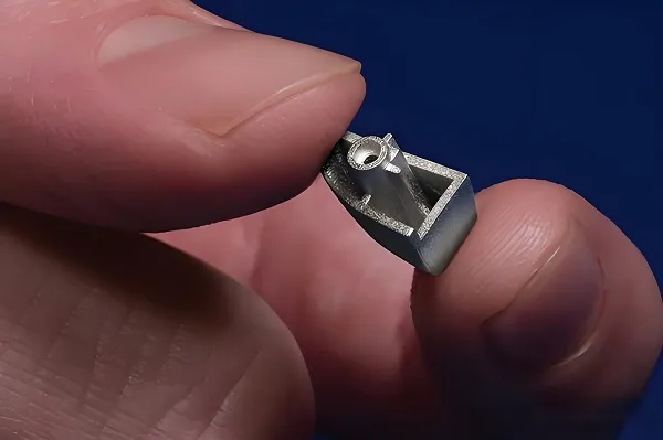
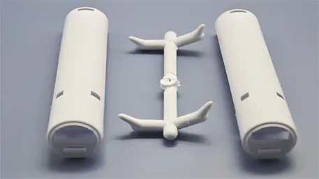
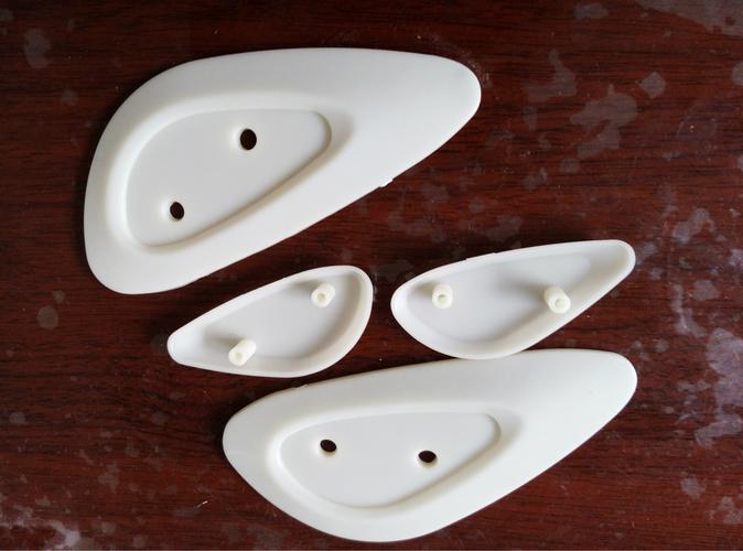
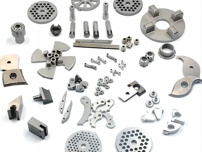
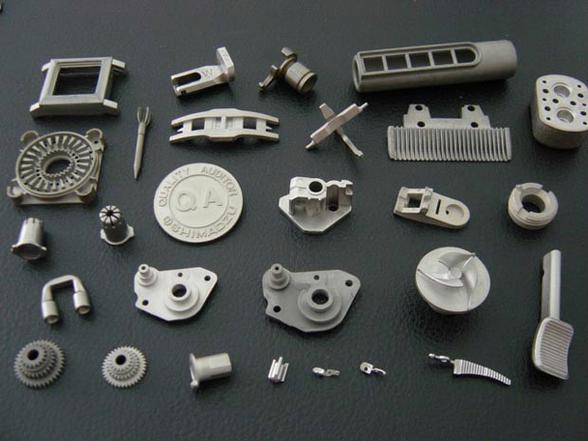
Metal Injection Molding (MIM) combines plastic injection molding with powder metallurgy to produce complex metal parts by mixing fine metal powders with binders, injecting into molds, removing binders, and sintering into dense components.
MIM Materials Properties
|
Material
|
Density (g/cc)
|
Tensile Strength (ksi)
|
Hardness
|
Applications
|
|
316L Stainless Steel
|
7.7
|
75
|
67 HRB
|
Medical, Consumer
|
|
17-4 PH Stainless Steel
|
7.6
|
130
|
32 HRC
|
Aerospace, Automotive
|
|
Ti-6Al-4V Titanium
|
4.4
|
120
|
35 HRC
|
Medical Implants
|
|
Low Alloy Steel
|
7.6
|
60
|
69 HRB
|
Structural
|
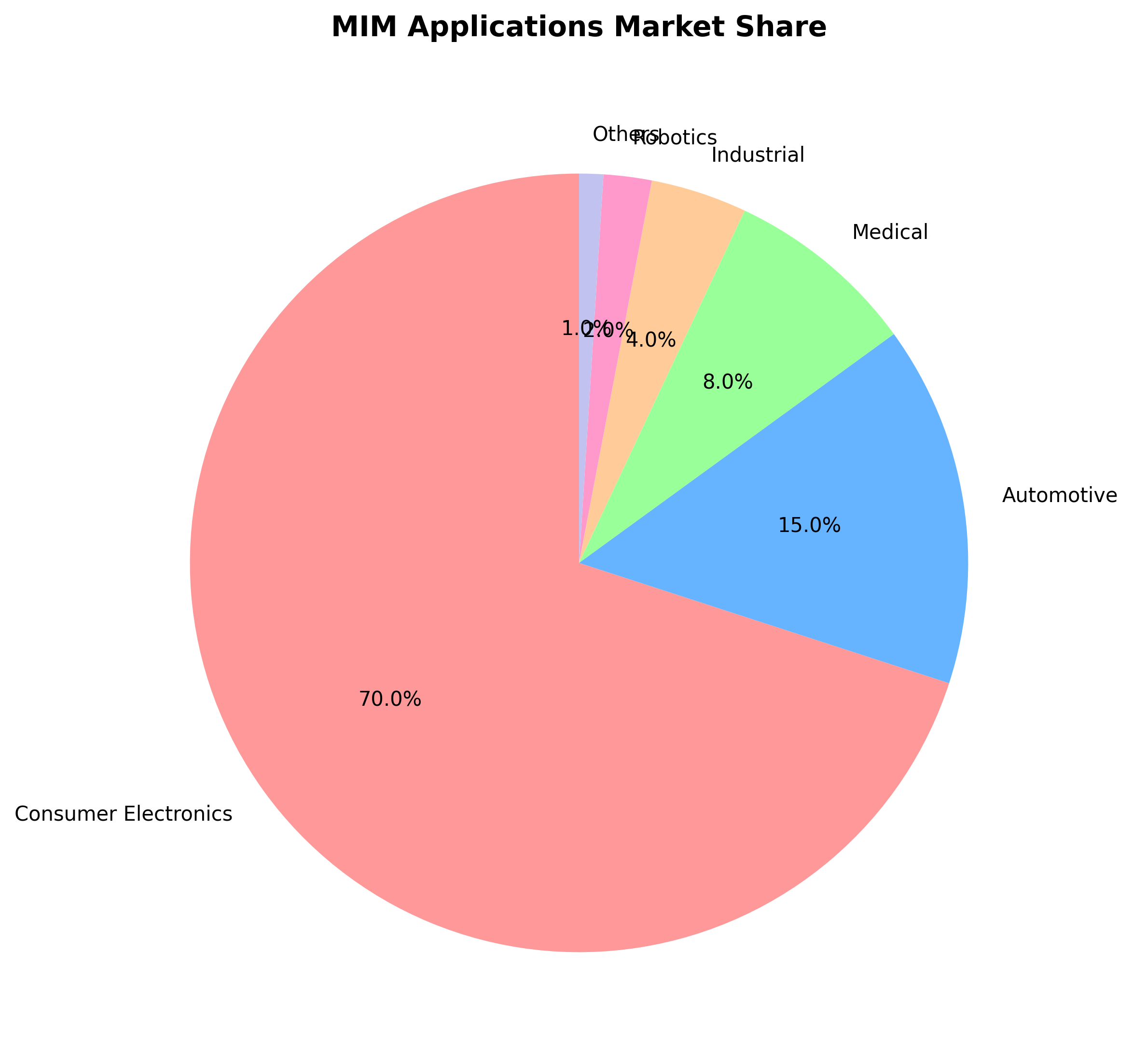
MIM Applications Market Share
MIM vs Traditional Manufacturing
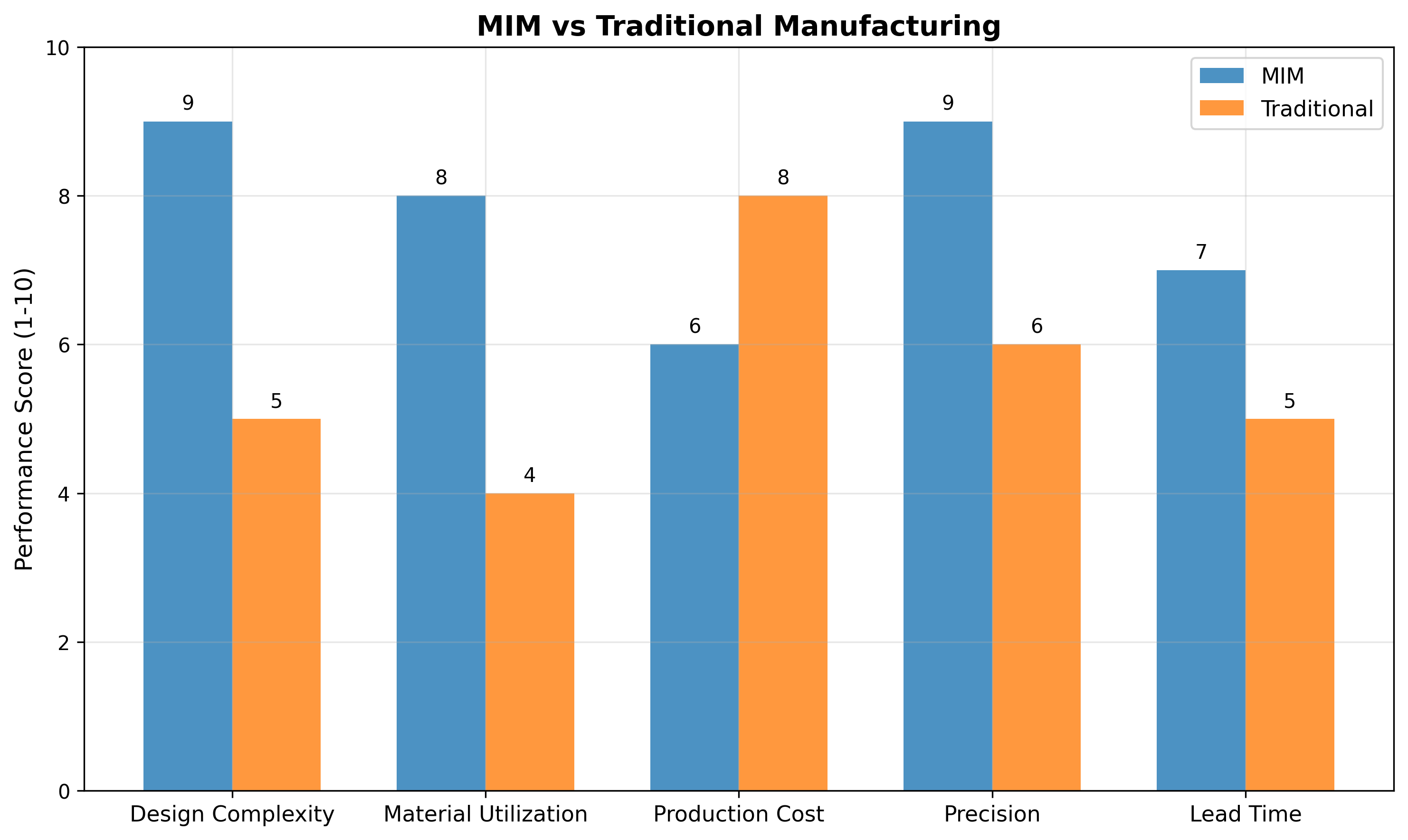
MIM mixes metal powders (2-25 microns) with binders to create injectable feedstock. After molding, binders are removed and parts are sintered at high temperatures to fuse metal particles.
The global MIM market grows at 10.7% CAGR, reaching $80.98 billion by 2030. Consumer electronics leads at 70%, followed by automotive at 15%. MIM excels at small, complex parts with high precision and material utilization, ideal for medical devices, aerospace, and consumer products.
Professional Knowledge about MIM
MIM Process Fundamentals
- Feedstock Preparation: Metal powders (2-25μm) mixed with binders (wax, polymer) at 60:40 ratio
- Injection Molding: Feedstock heated to 150-200°C and injected into molds at high pressure
- Debinding: Binders removed via solvent extraction, thermal decomposition, or catalytic process
- Sintering: Parts heated to 80-90% of melting temperature in controlled atmosphere
- Secondary Operations: Optional heat treatment, machining, plating, or assembly
Material Requirements
- Powder Characteristics: Spherical shape, narrow size distribution, high purity
- Binder Systems: Thermoplastic, wax-based, or water-soluble formulations
- Critical Properties: Flowability, thermal stability, debinding efficiency
- Common Materials: Stainless steels, titanium alloys, tool steels, superalloys
Design Considerations
- Wall Thickness: 0.2-6mm (optimal 1-3mm)
- Draft Angles: 0.5-2° for mold release
- Radii: Minimum 0.2mm internal radii
- Undercuts: Possible with split molds or collapsible cores
- Shrinkage: 12-25% linear shrinkage during sintering
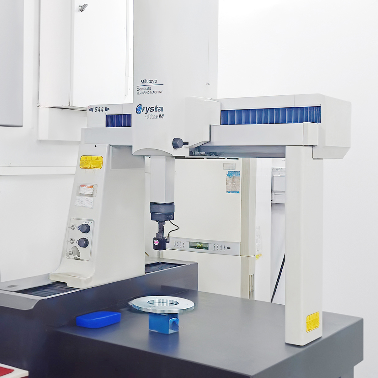
Quality Control Parameters
- Density: 95-99% of theoretical density
- Dimensional Tolerance: ±0.3% for most dimensions
- Surface Finish: 1-3μm Ra as-sintered
- Mechanical Properties: Comparable to wrought materials
- Microstructure: Homogeneous, fine-grained structure
Frequently Asked Questions (FAQ)
Q1: What size parts can MIM produce?
A: MIM typically produces small to medium parts weighing 0.1g to 200g, with dimensions up to 150mm.
Q2: How accurate are MIM parts?
A: Typical tolerances are ±0.3% of dimension, with critical features achievable at ±0.1%.
Q3: What is the minimum order quantity for MIM?
A: Economical production starts at 10,000 parts due to tooling costs (50,000).
Q4: How long does MIM production take?
A: Tooling lead time is 4-8 weeks, with production rates of 10,000-100,000 parts per week.
Q5: Can MIM produce porous parts?
A: Yes, controlled porosity (10-30%) is achievable for filters, bearings, and medical implants.
Q6: What post-processing is required for MIM parts?
A: Most parts need no post-processing, but options include heat treatment, machining, plating, and welding.
Q7: How does MIM compare to 3D printing for metal parts?
A: MIM offers higher production rates, better material properties, and lower cost for high-volume production, while 3D printing excels at low volumes and complex geometries.
Q8: What industries commonly use MIM?
A: Automotive, medical, aerospace, consumer electronics, firearms, and industrial equipment.
Disclaimer
All experimental data presented in this paper are derived from controlled production environments and standardized test procedures. However, due to differences in equipment models, material batches, and on-site operating conditions, readers are advised to verify and adjust technical parameters according to their specific application scenarios before practical implementation.
The research results and technical insights shared herein are based on the author’s professional experience and experimental observations. The author and the affiliated institution shall not be liable for any direct, indirect, or consequential damages (including but not limited to equipment damage, product quality issues, or production losses) arising from the improper use of the information provided in this paper.