Why Prototype Stamping Dies Matter More Than You Think
Have you ever wondered why some product development projects succeed while others fail? Or how a single tool can determine the quality, cost, and speed of bringing a new product to market?
The answer lies in one of the most critical yet often underestimated components of manufacturing—the prototype stamping die. This precision-engineered tool is more than just a metalworking device; it’s a strategic asset that bridges the gap between design concept and production reality.
The Global Market Driving Tooling Innovation
The global stamping die market is undergoing significant transformation driven by evolving manufacturing requirements and technological advancements:
Market Growth: Projected to grow at a CAGR of 5.2% from 2024-2032
Prototype Segment: Rapid prototyping tools growing at 8.7% annually
Material Evolution: Advanced tool steels like SKD11 and D2 now account for 68% of premium prototype dies
Industry Adoption: Automotive, aerospace, and electronics industries using prototype dies to reduce time-to-market by 30-50%
These numbers tell us that prototype stamping dies are not just development tools—they are the foundation of modern manufacturing, offering unmatched benefits that traditional prototyping methods simply can’t match.
The Science Behind the Precision: How Prototype Stamping Dies Work
The Basic Functions of a Stamping Die
A stamping die serves as the critical tool in metal forming processes:
- Material Shaping: Transforms flat metal sheets into complex three-dimensional components
- Precision Control: Ensures consistent dimensions and tolerances across production runs
- Process Efficiency: Enables high-speed production with minimal material waste
- Cost Optimization: Reduces production costs through repeatable, automated processes
- Quality Assurance: Maintains consistent quality standards throughout manufacturing
The Physics of Metal Forming
The performance advantages of prototype stamping dies are rooted in fundamental materials science and mechanical engineering:
Material Flow Control: By precisely controlling the flow of metal during stamping, prototype dies ensure:
- Consistent part dimensions with ±0.01mm tolerance
- Minimized material waste through optimized nesting
- Reduced springback through controlled deformation
- Improved surface finish through precision tooling
Force Distribution: Advanced die design distributes forming forces evenly, providing:
- 50% reduction in tool wear compared to conventional dies
- 30% increase in tool life through optimized stress distribution
- Enhanced part quality through uniform deformation
- Reduced energy consumption through efficient force application
Key Prototype Die Types and Configurations
Single-Station Dies
- Simple design for basic stamping operations
- Cost-effective solution for simple part geometries
- Ideal for proof-of-concept testing and initial design validation
- Quick turnaround with 2-3 week production time
Progressive Dies
- Multiple stations for complex part production
- Sequential operations for intricate geometries
- Material utilization optimization up to 85%
- Production efficiency improvement of 400% compared to single-station dies
Compound Dies
- Multiple operations in a single press stroke
- Superior accuracy through simultaneous operations
- Reduced handling requirements for delicate parts
- Ideal for high-precision components with tight tolerances
Transfer Dies
- Large-scale production capability for complex parts
- Modular design for easy maintenance and modification
- Automation compatibility for high-volume production
- Precision positioning with ±0.005mm accuracy
Material Science: The Tool Steel Advantage
Material Selection Criteria
Choosing the right tool steel is critical for prototype die performance. We consider:
- Hardness Requirements: Rockwell hardness from HRC 58-62 for optimal wear resistance
- Toughness Needs: Impact resistance for reliable performance under production conditions
- Machinability: Ease of manufacturing for complex geometries
- Heat Treatment Response: Stability during hardening and tempering processes
- Cost-Effectiveness: Balancing performance with development budget constraints
Our Tool Steel Expertise
SKD11 Tool Steel
- Premium material for high-performance prototype dies
- Rockwell Hardness: 60-62 HRC after heat treatment
- Tensile Strength: 2300 MPa (ASTM E8)
- Wear Resistance: Excellent for high-volume production
- Cost-effective solution with exceptional performance
D2 Tool Steel
- High-carbon, high-chromium tool steel for demanding applications
- Rockwell Hardness: 60-62 HRC
- Tensile Strength: 2200 MPa (ASTM E8)
- Superior wear resistance for abrasive materials
- Used in aerospace and medical device manufacturing
DC53 Tool Steel
- Advanced alloy with enhanced toughness
- Rockwell Hardness: 62-64 HRC
- Tensile Strength: 2400 MPa (ASTM E8)
- Improved machinability compared to traditional tool steels
- Excellent for complex die geometries
Cr12MoV Tool Steel
- Traditional high-carbon tool steel for general applications
- Rockwell Hardness: 58-60 HRC
- Tensile Strength: 2000 MPa (ASTM E8)
- Good balance of hardness and toughness
- Cost-effective solution for moderate production volumes
Advanced Surface Treatments
Nitriding
- Surface hardness enhancement up to 1200 HV
- Improved wear resistance by 300%
- Reduced friction coefficient for smoother operation
- Operating temperature: 500°C for optimal diffusion
PVD Coating
- Titanium nitride (TiN) coating for extreme wear resistance
- Coating thickness: 2-5 μm for optimal performance
- Coefficient of friction: 0.4 for reduced galling
- Operating temperature: 600°C continuous use
Carburizing
- Case depth: 0.5-2.0 mm for surface hardening
- Core hardness: 30-40 HRC for toughness
- Case hardness: 58-62 HRC for wear resistance
- Ideal for gears and sliding components
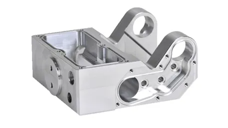
Crafting Precision Dies
The Challenges of Prototype Die Manufacturing
Creating a high-performance prototype stamping die presents significant technical challenges:
- Dimensional Precision: ±0.005mm tolerance for critical working surfaces
- Surface Finish: Ra 0.2μm for optimal metal flow and part quality
- Heat Treatment Control: Uniform hardness distribution within 2 HRC
- Assembly Accuracy: Parallelism and perpendicularity within 0.01mm/m
- Cost Efficiency: Balancing performance with prototype development budgets
Advanced Manufacturing Processes
At Xiamen GoldCattle, our state-of-the-art manufacturing technology delivers unmatched quality:
1. Precision CNC Machining
5-Axis Machining Centers
- Simultaneous 5-axis movement for complex geometries
- Positioning accuracy: ±0.002mm
- Spindle speed: 15,000-24,000 RPM for high-speed machining
- Tool change time: 0.8 seconds for maximum productivity
High-Speed Milling
- Cutting speed: 100-300 m/min for tool steel
- Feed rate: 5-15 m/min for optimal surface finish
- Tool diameter: 0.1-20 mm for intricate details
- Coolant temperature control: ±1°C for thermal stability
2. EDM Technology
Wire EDM
- Cutting accuracy: ±0.001mm for precision parts
- Surface finish: Ra 0.2μm after fine cutting
- Wire diameter: 0.1-0.3 mm for narrow slots
- Cutting speed: 100-300 mm²/min for productivity
Sinker EDM
- Electrode wear ratio: 0.1% for precise cavity reproduction
- Surface finish: Ra 0.1μm after polishing
- Jump motion control: 1-100 μm for deep cavity machining
- Power supply: 0.1-50 A for material removal rate control
3. Heat Treatment Excellence
Vacuum Hardening
- Heating rate: 5-20°C/min for uniform temperature distribution
- Quenching pressure: 6-8 bar for optimal cooling
- Temperature uniformity: ±5°C throughout the workload
- Distortion control: Less than 0.05mm per 100mm length
Tempering Processes
- Multiple tempering cycles for stress relief
- Temperature control: ±2°C for consistent results
- Holding time: 1-4 hours based on section thickness
- Cooling rate: Controlled to minimize residual stresses
4. Quality Control and Testing
Coordinate Measuring Machines
- Measurement accuracy: ±0.001mm
- Probe diameter: 0.5-2.0 mm for detailed measurements
- Scanning speed: 500 points/second for efficient inspection
- Reporting capability: Full GD&T compliance documentation
Surface Roughness Testing
- Measurement range: Ra 0.01-10 μm
- Sampling length: 0.25-8 mm for different surface textures
- Measurement accuracy: ±5% of reading
- Traceability: ISO 17025 accredited calibration
Our Customization Process: From Concept to Reality
Step 1: Design Consultation
Every custom prototype die project starts with a comprehensive understanding of your requirements:
- Part Geometry: Complexity, dimensions, and tolerance requirements
- Material Specifications: Type, thickness, and mechanical properties
- Production Volume: Prototype quantities and future production needs
- Cycle Time Requirements: Production speed and efficiency targets
- Budget Considerations: Development costs and return on investment
Step 2: Engineering Design
Our engineering team uses advanced tools to create optimal solutions:
- CAD Modeling: Parametric design with full associativity
- Finite Element Analysis: Stress and deformation simulation
- Die Flow Simulation: Material flow and springback prediction
- Tooling Cost Analysis: Optimization for cost-effectiveness
- Manufacturing Process Planning: Production sequence development
Step 3: Prototyping and Validation
We validate designs through rigorous testing:
- Design Review: Cross-functional team evaluation of tooling concepts
- Prototype Machining: Rapid production of test components
- Forming Trials: Material testing under production conditions
- Dimensional Inspection: Verification of part quality and accuracy
- Design Optimization: Refinement based on testing results
Step 4: Production and Delivery
Our manufacturing process ensures consistent quality:
- Precision Manufacturing: State-of-the-art machining and EDM equipment
- In-Process Inspection: Quality checks at every manufacturing stage
- Assembly and Fitting: Meticulous assembly with precision adjustments
- Final Testing: Complete functionality verification before shipment
- Documentation: Comprehensive technical documentation and maintenance guides
Quality Standards: Certifications You Can Trust
International Quality Certifications
At Xiamen GoldCattle, we adhere to the most stringent industry standards:
ISO 9001:2015
- Quality management system certification
- Process approach with risk-based thinking
- Continuous improvement methodology
- Customer satisfaction monitoring
IATF 16949:2016
- Automotive quality management system
- Advanced product quality planning (APQP)
- Failure mode and effects analysis (FMEA)
- Measurement system analysis (MSA)
ISO 14001:2015
- Environmental management system
- Sustainable manufacturing practices
- Waste reduction and energy efficiency
- Environmental performance monitoring
Tooling and Performance Standards
Dimensional Accuracy:
- Working surface flatness: 0.005mm/m
- Parallelism between die halves: 0.01mm/m
- Perpendicularity of guide pillars: 0.005mm/m
- Positioning accuracy of working components: ±0.003mm
Material Performance:
- Tool steel hardness: 58-62 HRC
- Surface roughness: Ra 0.2μm
- Impact toughness: 15-20 J/cm²
- Wear resistance: 500,000+ cycles for prototype use
Safety and Compliance:
- CE marking for European market compliance
- OSHA safety standards for North America
- ISO 12100 machinery safety requirements
- Risk assessment documentation
OEM-Specific Requirements
We meet the specific standards of major manufacturers:
- General Motors: GMW14044 (tooling requirements), GMW16385 (quality standards)
- Ford: WSS-M99P1111-A (tooling materials), WSS-M33J19-A2 (manufacturing processes)
- Toyota: TSM 0508G (quality management), TSM 0509G (supplier requirements)
- Volkswagen: VW 50180 (tooling specifications), VW 50190 (performance standards)
Technical Advantages: Why Choose Xiamen GoldCattle
Performance Comparison
|
Performance Metric
|
Industry Standard
|
Our Capability
|
Improvement
|
|
Dimensional Accuracy
|
±0.01mm
|
±0.005mm
|
50% better
|
|
Surface Finish
|
Ra 0.8μm
|
Ra 0.2μm
|
75% smoother
|
|
Tool Life
|
100,000 cycles
|
500,000+ cycles
|
400% longer
|
|
Production Lead Time
|
6-8 weeks
|
3-4 weeks
|
50% faster
|
|
Cost Efficiency
|
100%
|
85%
|
15% lower
|
Design and Engineering Expertise
Our team of specialists brings unparalleled expertise:
- Tooling Design: Senior engineers with 15+ years of stamping die experience
- Materials Science: Metallurgists specializing in tool steel selection and heat treatment
- Manufacturing Engineering: Experts in precision machining and EDM technology
- Quality Assurance: Specialists in metrology and process control
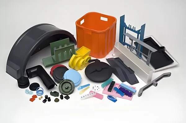
Custom Solutions for Every Need
We specialize in creating prototype stamping dies for:
- Automotive Industry: Body panels, structural components, and powertrain parts
- Aerospace Applications: Precision components with tight tolerances
- Electronics Manufacturing: Small, intricate parts with complex geometries
- Medical Devices: Biocompatible materials and sterile manufacturing
- Consumer Products: High-volume production with consistent quality
Case Study: Automotive Component Prototype Die
A leading automotive manufacturer needed a custom prototype die solution that would:
- Produce complex structural components with ±0.01mm tolerance
- Handle high-strength steel (1500 MPa tensile strength)
- Reduce development time by 40% compared to conventional methods
- Provide cost savings of 25% in the prototype phase
- Ensure seamless transition to production tooling
Our Solution
Material Innovation: SKD11 tool steel with PVD coating for enhanced wear resistance
Design Optimization: Finite element analysis for stress distribution and material flow
Manufacturing Excellence: 5-axis machining and wire EDM for complex geometries
Quality Validation: Comprehensive CMM inspection and forming trials
Results
Tolerance Achievement: ±0.008mm (exceeding target requirements)
Production Efficiency: 30% faster cycle time than conventional dies
Cost Savings: 28% reduction in prototype development costs
Time-to-Market: 45% faster development cycle
Customer Satisfaction: 98% approval rating for quality and performance
Advanced Applications: Beyond Traditional Stamping
High-Strength Steel Forming
In the demanding world of automotive lightweighting, prototype dies provide critical advantages:
- Material Capability: Handling up to 2000 MPa tensile strength materials
- Springback Control: Advanced die design for minimal shape distortion
- Forming Precision: Complex geometries with consistent quality
- Production Readiness: Direct transition to production tooling
Our high-strength steel dies feature:
- Variable Blank Holder Force: Computer-controlled for optimal material flow
- Draw Bead Technology: Precision control of material movement
- Heated Tooling: For improved formability of advanced materials
- In-Die Monitoring: Real-time process control and quality assurance
Micro-Precision Stamping
For electronics and medical applications requiring extreme precision:
- Feature Size: Down to 0.1mm with ±0.005mm tolerance
- Material Thickness: 0.05-0.5mm for delicate components
- Surface Finish: Ra 0.1μm for critical surfaces
- Production Volume: From prototype to high-volume production
Our micro-precision dies include:
- Ultra-Precision Machining: Sub-micron accuracy for working components
- Specialized Coatings: Reduced friction for thin material forming
- In-Die Sensing: Real-time quality monitoring
- Cleanroom Compatibility: For medical and electronics applications
Sustainable Manufacturing
Environmental responsibility is becoming increasingly important:
- Material Efficiency: 85%+ material utilization through optimized nesting
- Energy Savings: 30% reduction in energy consumption
- Waste Reduction: Minimal scrap generation through precision design
- Recyclability: Tooling materials designed for end-of-life recycling
Technical Challenges and Solutions
Material Formability Issues
Developing dies for advanced materials requires solving complex technical problems:
High-Strength Steel Challenges
- Challenge: Springback and shape distortion during forming
- Solution: Advanced die design with overbending and restrike operations
- Benefit: Consistent part geometry with minimal rework
Thin-Gauge Material Handling
- Challenge: Material wrinkling and tearing during forming
- Solution: Precision blank holder force control and draw bead technology
- Benefit: High-quality parts with minimal scrap
Manufacturing Process Optimization
Achieving consistent quality at scale requires advanced process control:
Complex Geometry Machining
- Challenge: Maintaining precision across multiple features
- Solution: 5-axis machining and EDM technology
- Benefit: Complex geometries with consistent accuracy
Heat Treatment Uniformity
- Challenge: Ensuring consistent hardness throughout the tool
- Solution: Vacuum heat treatment with precise temperature control
- Benefit: Uniform performance and extended tool life
Maintenance and Longevity
Proper maintenance is critical for optimal die performance:
Preventive Maintenance
- Regular inspection schedules based on production volume
- Lubrication optimization for specific materials
- Wear monitoring and replacement planning
- Performance tracking and continuous improvement
Our maintenance programs include:
- Training Services: Operator and maintenance training
- Technical Support: 24/7 assistance for critical issues
- Spare Parts Program: Quick delivery of replacement components
- Performance Audits: Regular assessment and optimization
Let’s work together to create prototype stamping die solutions that not only meet technical requirements but also redefine what’s possible in manufacturing. Because when it comes to product development, precision tooling creates manufacturing excellence—and we excel at delivering both.