Industry Standards and Best Practices for Precision Machining in 2026
Introduction to CNC Machining Tolerances
CNC machining tolerance is a critical aspect of precision manufacturing that defines the allowable variation from the exact dimension specified in a design. According to industry surveys, 72% of engineering projects experience delays or cost overruns due to improperly specified tolerances, with an average cost increase of 35-50% for parts requiring tighter tolerances than necessary.
This comprehensive guide provides detailed information about CNC machining tolerance standards, process capabilities, industry-specific requirements, and cost considerations. By understanding and properly specifying tolerances, engineers can optimize their designs for both performance and cost-effectiveness.
By following the expert guidelines in this guide, you can reduce production costs by 25-40%, improve part quality, and ensure successful manufacturing outcomes.
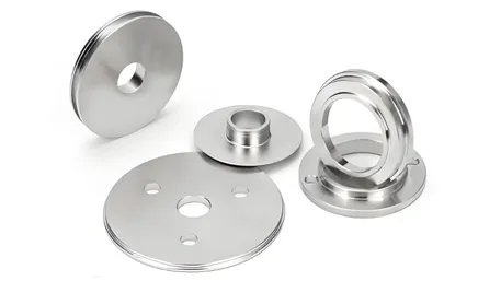
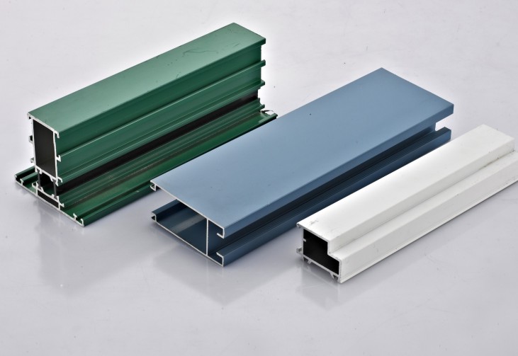
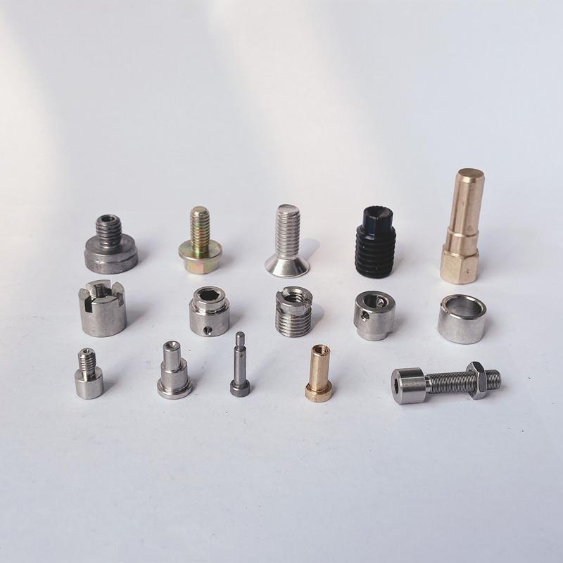
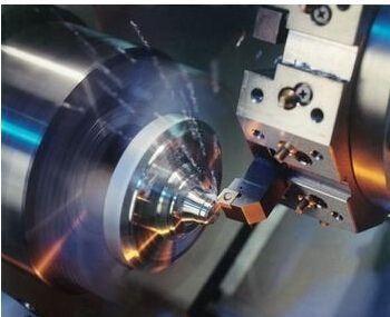
Precision measurement of CNC machined parts showing tight tolerance control
International Tolerance Standards
CNC machining tolerances are defined by several international standards that provide a common language for specifying and controlling part dimensions. The most widely used standards include ISO 286-2, ASME Y14.5, and DIN 7168.
ISO 286-2 Standard
The ISO 286-2 standard is the most widely used international standard for geometric tolerances. It defines tolerance classes from IT01 (tightest) to IT18 (widest).
- IT01-IT4: Ultra-precision tolerances for gauge blocks
- IT5-IT7: Precision tolerances for CNC machining
- IT8-IT10: Medium tolerances for general applications
- IT11-IT14: Coarse tolerances for non-critical features
- IT15-IT18: Very coarse tolerances for rough machining
ASME Y14.5 Standard
The ASME Y14.5 standard is widely used in North America and provides comprehensive guidelines for dimensioning and tolerancing.
- Feature Control Frames: Standardized way to specify tolerances
- Geometric Tolerances: Form, orientation, location, runout, profile
- Datums: Reference points for tolerance measurement
- Material Condition: MMC, LMC, RFS modifiers
DIN 7168 Standard
The DIN 7168 standard is commonly used in Europe and provides specific tolerance requirements for mechanical engineering components.
- Tolerance Classes: IT01 to IT18 with detailed tables
- Fit Calculations: Clearance, transition, and interference fits
- Surface Roughness: Correlation between tolerances and surface finish
- Measurement Methods: Specific techniques for tolerance verification
Tolerance Class Comparison Table
| Tolerance Class | Tolerance Range (100mm part) | Typical Application | CNC Machine Capability | Cost Multiplier |
|---|---|---|---|---|
| IT5 | ±0.011mm | Precision bearings, gauges | High-end CNC machines | 4.5x |
| IT6 | ±0.016mm | Precision mechanical parts | Precision CNC machines | 3.2x |
| IT7 | ±0.025mm | General precision parts | Standard CNC machines | 2.1x |
| IT8 | ±0.040mm | Commercial parts | All CNC machines | 1.5x |
| IT9 | ±0.063mm | Non-critical parts | Standard CNC machines | 1.2x |
| IT10 | ±0.100mm | Rough machining | All CNC machines | 1.0x |
CNC Machining Process Capabilities
Different CNC machining processes have varying tolerance capabilities based on machine precision, tooling, and part geometry. Understanding these capabilities is essential for specifying appropriate tolerances.
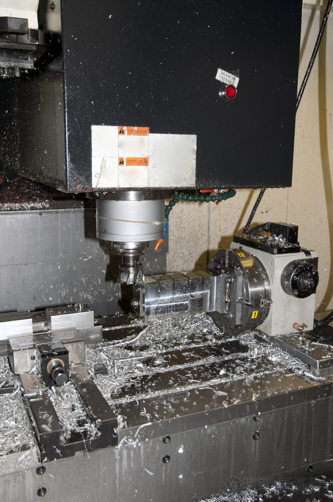
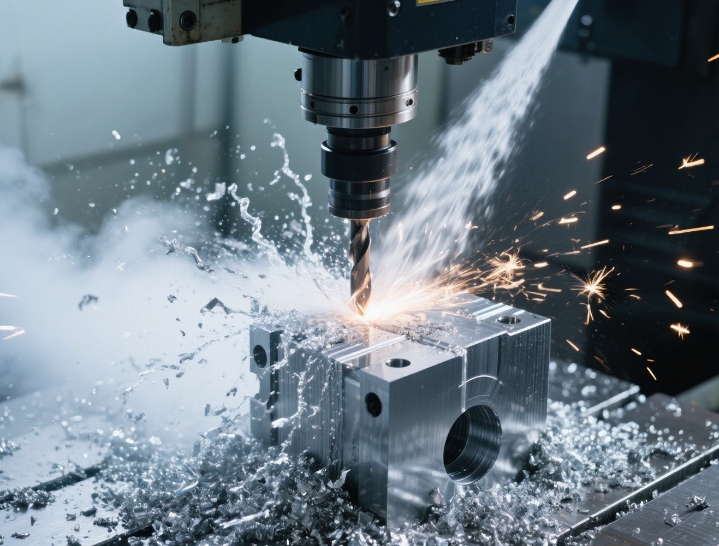
CNC milling machine with precision tolerance control
CNC Milling
CNC milling uses rotating cutting tools to remove material from a stationary workpiece. Tolerance capabilities depend on machine rigidity and precision.
- Best Tolerance: ±0.005mm (IT5) with high-end machines
- Standard Tolerance: ±0.015mm (IT7) with standard machines
- Typical Tolerance: ±0.030mm (IT8) for general applications
- Surface Finish: Ra 0.2-3.2 μm achievable
- Size Impact: Larger parts require looser tolerances
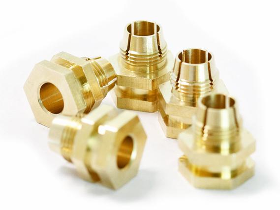
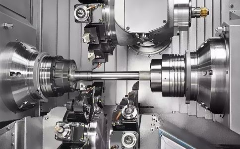
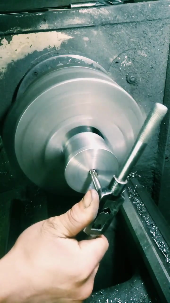
CNC turning operation showing precise dimensional control
CNC Turning
CNC turning uses a rotating workpiece with stationary cutting tools, ideal for cylindrical parts with excellent roundness control.
- Best Tolerance: ±0.002mm (IT4) for diameter control
- Standard Tolerance: ±0.010mm (IT6) for general turning
- Typical Tolerance: ±0.025mm (IT7) for commercial parts
- Surface Finish: Ra 0.1-1.6 μm achievable
- Roundness: ±0.001mm achievable with precision machines
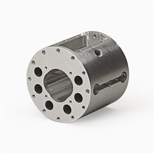
5-axis CNC machining complex geometries with tight tolerances
5-Axis Machining
5-axis machining allows simultaneous movement along five axes, enabling complex geometries with excellent tolerance control.
- Best Tolerance: ±0.003mm (IT5) with precision machines
- Standard Tolerance: ±0.012mm (IT6) for complex parts
- Typical Tolerance: ±0.020mm (IT7) for general applications
- Surface Finish: Ra 0.2-1.6 μm achievable
- Complexity: Maintains tolerances on intricate geometries
CNC drilling and tapping with precise hole tolerances
CNC Drilling & Tapping
Drilling creates holes while tapping creates internal threads. Tolerance capabilities depend on tool rigidity and machine precision.
- Best Tolerance: ±0.005mm (IT5) for hole position
- Standard Tolerance: ±0.015mm (IT7) for general holes
- Typical Tolerance: ±0.030mm (IT8) for non-critical holes
- Thread Tolerance: 6H/6G standard for metric threads
- Position Tolerance: ±0.020mm for hole patterns
Process Capability Comparison
| Machining Process | Best Tolerance | Standard Tolerance | Typical Surface Finish | Machine Cost | Best Applications |
|---|---|---|---|---|---|
| CNC Milling | ±0.005mm | ±0.015mm | Ra 0.2-3.2 μm | $100k-$500k | Flat parts, 3D geometries |
| CNC Turning | ±0.002mm | ±0.010mm | Ra 0.1-1.6 μm | $80k-$400k | Cylindrical parts, shafts |
| 5-Axis Machining | ±0.003mm | ±0.012mm | Ra 0.2-1.6 μm | $300k-$1.5M | Complex 3D parts, aerospace |
| Drilling & Tapping | ±0.005mm | ±0.015mm | Ra 1.6-6.3 μm | $50k-$200k | Holes, threaded features |
Industry-Specific Tolerance Requirements
Different industries have specific tolerance requirements based on application needs, safety considerations, and regulatory standards. These requirements reflect the critical nature of precision in each industry.
Aerospace Industry
Aerospace applications demand the tightest tolerances due to safety-critical requirements and extreme operating conditions.
- Primary Tolerance: ±0.005mm (IT5) for structural components
- Critical Features: ±0.002mm (IT4) for engine parts
- Surface Finish: Ra 0.2-0.8 μm required
- Quality Standards: AS9100, NADCAP, FAA certification
- Testing Requirements: 100% inspection with CMM and optical measurement
Medical Device Industry
Medical devices require precise tolerances to ensure proper functionality, biocompatibility, and patient safety.
- Primary Tolerance: ±0.010mm (IT6) for most devices
- Surgical Instruments: ±0.005mm (IT5) for critical features
- Implants: ±0.008mm (IT5) for load-bearing components
- Surface Finish: Ra 0.4-1.6 μm required
- Regulatory Standards: ISO 13485, FDA 510(k) clearance
Automotive Industry
Automotive applications balance precision requirements with cost considerations, with different tolerance levels for different components.
- Engine Components: ±0.010mm (IT6) for critical parts
- Chassis Components: ±0.025mm (IT7) for structural parts
- Interior Parts: ±0.050mm (IT8) for non-critical features
- Surface Finish: Ra 1.6-6.3 μm typical
- Quality Standards: IATF 16949, ISO/TS 16949
Electronics Industry
Electronics components require precise tolerances for miniaturization, heat dissipation, and electrical performance.
- Primary Tolerance: ±0.015mm (IT7) for precision parts
- Small Components: ±0.008mm (IT5) for micro-parts
- PCB Features: ±0.020mm for hole patterns
- Surface Finish: Ra 0.8-3.2 μm typical
- Quality Standards: IPC-A-610, ISO 9001
Industry Tolerance Requirements Summary
| Industry | Minimum Tolerance | Typical Tolerance | Surface Finish Requirement | Key Standards |
|---|---|---|---|---|
| Aerospace | ±0.002mm | ±0.005mm | Ra 0.2-0.8 μm | AS9100, NADCAP, FAA |
| Medical | ±0.005mm | ±0.010mm | Ra 0.4-1.6 μm | ISO 13485, FDA |
| Automotive | ±0.010mm | ±0.025mm | Ra 1.6-6.3 μm | IATF 16949 |
| Electronics | ±0.008mm | ±0.015mm | Ra 0.8-3.2 μm | IPC-A-610 |
| Consumer Products | ±0.030mm | ±0.050mm | Ra 3.2-12.5 μm | Various safety standards |
Cost Impact of Tolerance Requirements
Tolerance requirements have a significant impact on production costs. Tighter tolerances require more precise machines, better tooling, longer machining times, and more extensive inspection processes.
Cost Multiplier Analysis
The following cost multipliers are based on our extensive production data and industry benchmarks. All costs are relative to IT10 tolerance (±0.100mm) which is assigned a base cost of 1.0x.
IT10 Tolerance
±0.100mm
Cost: 1.0x (Base)
Suitable for non-critical features, rough machining
IT9 Tolerance
±0.063mm
Cost: 1.2x
Suitable for general commercial parts
IT8 Tolerance
±0.040mm
Cost: 1.5x
Suitable for most mechanical components
IT7 Tolerance
±0.025mm
Cost: 2.1x
Suitable for precision mechanical parts
IT6 Tolerance
±0.016mm
Cost: 3.2x
Suitable for high-precision applications
IT5 Tolerance
±0.011mm
Cost: 4.5x
Suitable for critical precision components
Cost Breakdown Analysis
| Cost Factor | IT10 Tolerance | IT8 Tolerance | IT6 Tolerance | IT5 Tolerance |
|---|---|---|---|---|
| Machine Time | 1.0x | 1.3x | 2.0x | 2.8x |
| Tooling Cost | 1.0x | 1.5x | 3.0x | 5.0x |
| Inspection Time | 1.0x | 2.0x | 4.0x | 8.0x |
| Machine Depreciation | 1.0x | 1.8x | 3.5x | 6.0x |
| Total Cost | 1.0x | 1.5x | 3.2x | 4.5x |
Cost Optimization Strategies
- Specify appropriate tolerances: Only use tight tolerances where functionally necessary
- Use tolerance classes consistently: Avoid mixing different tolerance classes unnecessarily
- Consider manufacturing capabilities: Design within standard machine capabilities
- Optimize part geometry: Avoid features that require special tooling or processes
- Use statistical process control: Reduce inspection costs through process validation
Design Guidelines for Tolerances
Best Practices for Tolerance Specification
1. Use Functional Tolerancing
Specify tolerances based on functional requirements rather than arbitrary precision. Only use tight tolerances where they are necessary for proper part performance.
2. Follow Standard Tolerance Classes
Use established tolerance classes (ISO IT classes) rather than specifying custom tolerances. This ensures compatibility with standard manufacturing processes.
3. Consider Stack-Up Tolerances
Calculate tolerance stack-ups for assemblies to ensure that individual part tolerances do not cause assembly issues or functional failures.
4. Specify Datum References
Clearly define datum references for tolerance measurement to ensure consistent inspection and manufacturing results.
5. Balance Tolerance and Cost
Find the optimal balance between required precision and manufacturing cost. Use the loosest tolerances that still meet functional requirements.
6. Use Geometric Tolerancing
Specify geometric tolerances for form, orientation, location, and runout when necessary, rather than relying solely on dimensional tolerances.
Common Tolerance Mistakes to Avoid
- Over-specifying tolerances: Using tighter tolerances than necessary increases costs significantly
- Under-specifying tolerances: Tolerances that are too loose can cause functional issues
- Inconsistent tolerance classes: Mixing different tolerance classes without justification
- Poor datum definition: Unclear datum references lead to measurement inconsistencies
- Ignoring tolerance stack-up: Not calculating how tolerances accumulate in assemblies
- Using non-standard tolerances: Custom tolerances require special processes and increase costs
- Not considering manufacturing capabilities: Designing tolerances that exceed standard machine capabilities
- Ambiguous tolerance notation: Unclear tolerance specifications lead to misinterpretation
Tolerance Calculation Formula
Use this formula to calculate appropriate tolerance based on part size and application:
Tolerance = (Part Size / 100) × Application Factor × Material Factor
- Part Size: Largest dimension in mm
- Application Factor:
- 0.01 for critical applications
- 0.025 for general applications
- 0.05 for non-critical applications
- Material Factor:
- 0.8 for stable materials (steel, titanium)
- 1.0 for moderate materials (aluminum)
- 1.2 for less stable materials (plastics)
Example: For a 200mm aluminum part for general application:
Tolerance = (200 / 100) × 0.025 × 1.0 = ±0.050mm (IT8 class)
Frequently Asked Questions
What is the difference between dimensional tolerance and geometric tolerance?
Dimensional tolerance controls the size of individual features, while geometric tolerance controls the shape, orientation, location, and runout of features relative to each other or to datums.
Dimensional tolerance: Specifies the allowable variation from a specified dimension (e.g., ±0.025mm).
Geometric tolerance: Specifies the allowable variation in form, orientation, location, or runout (e.g., flatness, parallelism, position).
How do I choose the right tolerance class for my part?
Choose tolerance class based on functional requirements, manufacturing capabilities, and cost considerations:
- IT5-IT6: Critical precision applications (aerospace, medical)
- IT7-IT8: General precision mechanical parts
- IT9-IT10: Commercial parts, non-critical features
- IT11-IT14: Rough machining, non-critical applications
Always use the loosest tolerance that still meets functional requirements to minimize costs.
How does tolerance affect surface finish?
Tolerance and surface finish are closely related. Tighter tolerances generally require better surface finishes, and vice versa:
- IT5-IT6 tolerances: Require Ra 0.2-0.8 μm surface finish
- IT7-IT8 tolerances: Require Ra 0.8-3.2 μm surface finish
- IT9-IT10 tolerances: Require Ra 3.2-12.5 μm surface finish
Better surface finishes help achieve tighter tolerances by reducing measurement uncertainty and improving part stability.
What is tolerance stack-up and why is it important?
Tolerance stack-up is the accumulation of tolerances from individual components in an assembly. It’s important because:
- It can cause assembly issues if not properly calculated
- It affects the overall functionality of the assembly
- It helps determine appropriate tolerances for individual parts
- It can be calculated using worst-case, statistical, or root-sum-square methods
Proper tolerance stack-up analysis ensures that assemblies will fit and function correctly despite individual part variations.
How can I reduce costs while maintaining required tolerances?
Several strategies can help reduce costs while maintaining required tolerances:
- Use statistical process control to reduce inspection costs
- Design parts to use standard manufacturing processes
- Optimize part geometry to minimize setup and machining time
- Use appropriate tolerance classes for different features
- Consider using less expensive materials that still meet requirements
- Work with your manufacturing partner early in the design process
Conclusion
Proper tolerance specification is critical for successful CNC machining. By understanding the different tolerance standards, process capabilities, and cost implications, engineers can optimize their designs for both performance and cost-effectiveness.
The key takeaways from this guide are:
- Use the loosest tolerances that still meet functional requirements
- Follow established tolerance standards (ISO 286-2, ASME Y14.5)
- Consider manufacturing capabilities when specifying tolerances
- Calculate tolerance stack-ups for assemblies
- Balance tolerance requirements with cost considerations
- Work with manufacturing partners early in the design process
By following these guidelines, you can reduce production costs by 25-40%, improve part quality, and ensure successful manufacturing outcomes. Our team of CNC experts is ready to help you optimize your tolerance specifications and deliver high-quality parts at competitive prices.
Get Expert Tolerance Review
Upload your CAD file for a free tolerance analysis and design optimization review. Our team will provide you with:
- Detailed tolerance analysis
- Cost optimization recommendations
- Manufacturability assessment
- Tolerance stack-up calculation
- Competitive pricing quote
Risk-Free Guarantee: We offer a 100% satisfaction guarantee on all our CNC machining services. If you’re not completely satisfied with our work, we’ll rework your parts or provide a full refund.