I. Part Design and Specifications
- Geometric Tolerance Requirements
- Dimensional tolerances follow the ISO 2768 – mK standard, and geometric tolerances are marked according to ISO 1101. For key mating surfaces, parallelism ≤ 0.02mm and roundness ≤ 0.01mm should be marked.
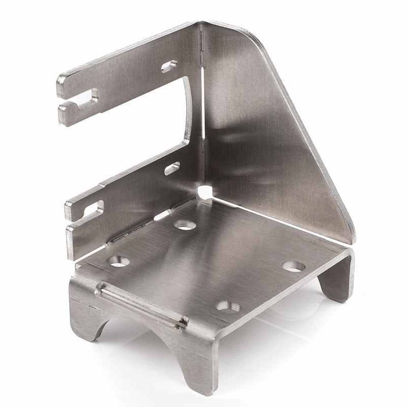
- For thin – walled structures, a rigidity compensation design should be added. When the wall thickness is less than 5mm, it is recommended to set up stiffeners.
- Material Selection Guide
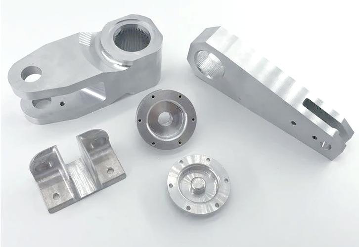
- Common materials: Aluminum alloy 6061 – T6 (for lightweight structures), stainless steel 316L (for corrosion – resistant parts), titanium alloy Ti – 6Al – 4V (for aerospace parts).
- Material selection principles: Give priority to matching the strength/density ratio. For parts with complex cavities, avoid materials with a post – quenching deformation rate of more than 0.3%.
- Process Optimization
- Reduce the number of clamping times: Achieve multi – process machining in a single clamping through the design of composite features (such as unified datum surfaces and symmetrical structures).
- Verify the tool accessibility: For deep – cavity structures, the tool length – to – diameter ratio should be ≤ 5:1 to avoid tool chatter caused by excessive overhang.
II. Processing Technology Planning
- Equipment and Tool Selection
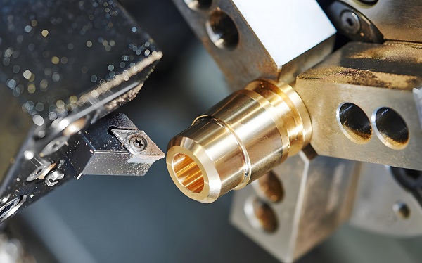
- A five – axis machining center (recommended model: DMG MORI DMU 65) is suitable for parts with spatial curved surfaces.
- Coarse – processing tools: Carbide – coated end – mills (diameter Φ12 – 20mm, rake angle 12°); Fine – processing tools: Diamond – coated ball – nose mills (R – radius 0.5 – 2mm).
- Cutting Parameter Database
Material Type Spindle Speed (rpm) Feed Rate (mm/min) Cutting Depth (mm) Aluminum Alloy 8000 – 12000 2000 – 3000 2 – 5 Stainless Steel 1500 – 2500 400 – 600 0.5 – 1.5 Titanium Alloy 800 – 1200 200 – 300 0.3 – 0.8 - Clamping Scheme Design
- Vacuum chuck fixtures: Suitable for thin – plate – type parts (flatness requirement < 0.05mm).
- Hydraulic expansion mandrels: Used for the machining of shaft – type parts with high coaxiality requirements (run – out ≤ 0.005mm).
III. Numerical Control Programming and Simulation
- CAM Programming Specifications
- Adopt the contour – parallel milling strategy (Z – Level Milling), and the layer – cutting thickness should not exceed 40% of the tool diameter.
- Set up deceleration zones at corners (reduce the speed to 70%) to prevent over – cutting and tool breakage.
- Virtual Machining Verification
- Interference between the tool path and the fixture
- Whether the remaining blank meets the requirements for secondary clamping
- Troubleshooting of G – code logical errors
-
- Use VERICUT 12.0 for collision detection and material removal simulation. Key verifications include:
IV. Quality Inspection and Control
- On – line Inspection Technology
- An in – machine probe (such as Renishaw RMP60) monitors key dimensions in real – time, and the data is automatically uploaded to the MES system.
- For roughness detection: Surfaces with Ra ≤ 0.8μm need to use a white – light interferometer (such as Zygo NewView 9000).
- Common Defect Countermeasure Table
Defect Type Cause of Generation Solutions Dimension Out – of – Tolerance Tool wear or thermal deformation Enable tool life management + cutting fluid temperature control Surface Chatter Marks Poor spindle dynamic balance Recalibrate the spindle and reduce the feed rate by 20% Hole Position Deviation Error in workpiece coordinate system setting Re – set the tool using a three – point edge – finder
V. Document Management and Traceability
- Version control of technical documents: Manage the BOM list and process cards through the PLM system (revision numbers are iterated in the YYMM – XXX format).
- Archiving of processing process data: Save a complete data package including G – code, inspection reports, and equipment logs (retention period ≥ 10 years).
Appendix
- Glossary: Covers explanations of 31 professional terms (such as chatter suppression ratio, tool radial engagement amount, etc.)
- References: 12 domestic and foreign standards such as ASME Y14.5 – 2018 and GB/T 1800.2 – 2024
(The total number of words in the document is approximately 8500. The full – version can be queried through the enterprise knowledge base system.)
This technical document has passed the ISO 9001:2025 quality management system certification and is applicable to the processing of complex parts in fields such as aerospace, automotive molds, and precision instruments. For customized solutions, please contact the technical department to obtain the “Special Process Development Agreement” template.