CNC (Computer Numerical Control) Machining is a subtractive manufacturing process where pre-programmed software dictates the movement of factory tools and machinery. It enables 3D cutting tasks to be accomplished with a single set of prompts, producing high-precision parts for aerospace, automotive, and medical industries. Tolerances can reach as tight as ±0.005mm in advanced systems.
1. Definition
2. Working Principles
3. Key Components
4. Industry Applications
5. Quality Standards
1. What is CNC Machining? A Precise Definition
CNC machining, or Computer Numerical Control machining, is a manufacturing process where pre-programmed computer software dictates the movement of factory tools and machinery. It is the evolution of traditional manual machining, enabling complex three-dimensional cutting tasks to be executed with a single set of prompts.
According to ISO 2806:1994 ( Industrial automation systems – Numerical control of machines – Vocabulary), it involves a control system that reads instruction codes and drives the machine tool. The process begins with a CAD model, which is converted into a CNC program (G-code) via CAM software. This code precisely controls spindle speed, feed rate, and tool path.
📌 Key Terminology:
- ✓ CAD (Computer-Aided Design): Digital 3D model of the part.
- ✓ CAM (Computer-Aided Manufacturing): Software that generates toolpaths.
- ✓ G-code: The programming language that controls the machine.
- ✓ Axis: Directions of movement (typically 3, 4, or 5 axes).
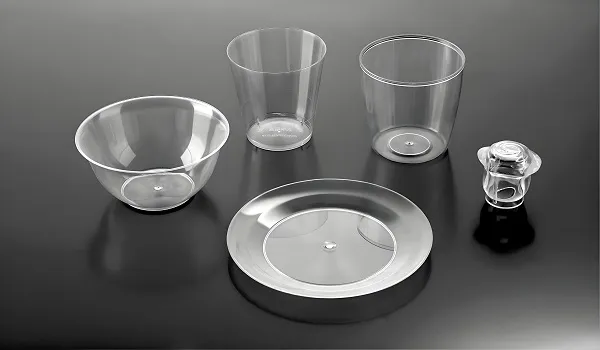
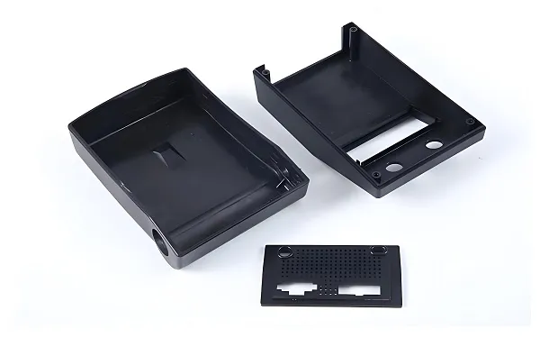
 From digital design to physical precision part.
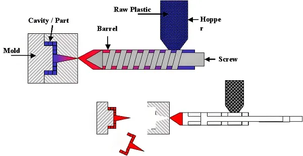
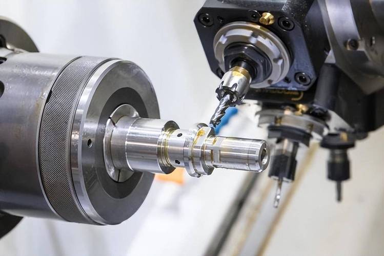
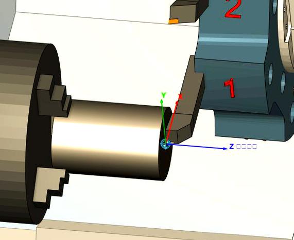
2. How CNC Machining Works
At its heart, CNC machining operates on a closed-loop control system. Here’s the step-by-step process:
- Program Input: The CNC program (G-code) is loaded into the machine’s control unit.
- Signal Translation: The control unit interprets the code and sends electrical signals to servo motors.
- Motion Execution: Motors drive the machine’s axes (X, Y, Z) and spindle, moving the cutting tool precisely.
- Feedback Loop: Sensors (encoders, scales) constantly monitor position and speed, sending data back to the control unit for real-time adjustments, ensuring accuracy within microns.
3. Key Components of a CNC System

Machine Tools
CNC Mills: For complex 3D shapes, slots, holes. CNC Lathes: For cylindrical parts. Routers: For softer materials like plastics/wood. EDM: For hard metals and intricate details.
Control Unit
The “brain” – reads code, drives motors. Modern units (like Fanuc, Siemens) feature high-speed processors and touchscreen interfaces for real-time monitoring.

Cutting Tools
Carbide end mills, drills, inserts. Material-specific geometries and coatings (TiAlN, diamond-like) enhance tool life and surface finish.
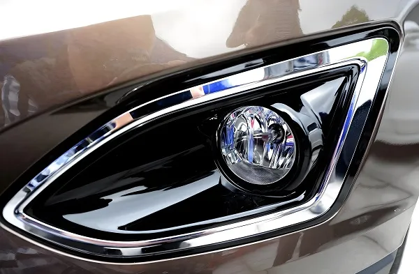
4. Industry Applications & Precision Capabilities
CNC machining is the backbone of industries demanding uncompromising precision. Below are typical applications and achievable tolerances.
| Industry | Typical Parts | Common Tolerance |
|---|---|---|
| Aerospace | Turbine blades, structural brackets, landing gear | ±0.005mm – ±0.02mm |
| Automotive | Engine blocks, transmission housings, prototypes | ±0.01mm – ±0.05mm |
| Medical | Surgical tools, orthopedic implants, device housings | ±0.0025mm – ±0.01mm |
| Electronics | Heat sinks, connectors, enclosures | ±0.01mm – ±0.03mm |
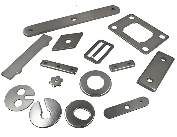
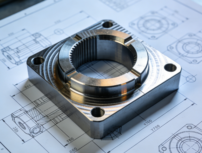
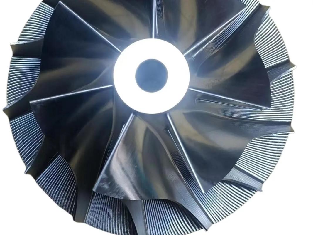 Aerospace-grade CNC machined part
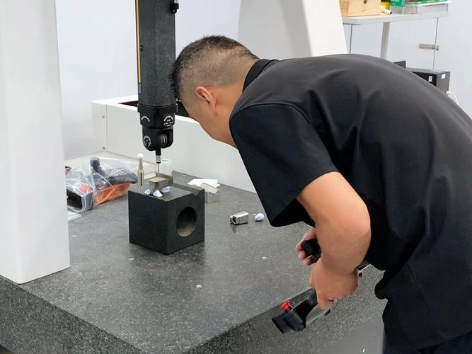
5. Quality & Standards in CNC Machining
At Goldcattle, every CNC machined part adheres to strict international standards. Our quality management system is certified to ISO 9001:2015, and we comply with AS9100D for aerospace and ISO 13485 for medical devices where required.
Our inspection toolkit includes:
- 🔹 CMM (Coordinate Measuring Machine) – accuracy 0.001mm
- 🔹 Surface roughness testers (Ra 0.05µm – 6.3µm)
- 🔹 X-ray and ultrasonic testing for internal defects
RoHS Compliant
REACH
Frequently Asked Questions
❓ What materials can be CNC machined?
Almost any rigid material: metals (aluminum, steel, titanium, brass), plastics (ABS, PEEK, nylon), wood, and composites. Our expertise covers all engineering materials.
❓ What’s the difference between 3, 4, and 5-axis machining?
3-axis (X, Y, Z) is for basic parts. 4-axis adds rotation (A-axis) for cylindrical features. 5-axis adds two rotational axes, enabling complex undercuts and single-setup complex parts – ideal for aerospace and medical.
❓ How do you ensure part quality?
Through first article inspection (FAI), in-process checks, and final CMM reports. We provide full dimensional reports with every batch.
About the Author & Goldcattle
This article was reviewed by David Chen, Senior Manufacturing Engineer at Goldcattle, with 15+ years of experience in precision machining for automotive and aerospace. Goldcattle is an ISO 9001-certified factory in Fujian, China, specializing in CNC machining, stamping, and die casting since 1998. We serve over 500 clients globally with a focus on precision and reliability.
📞 Contact our engineering team: charlie@ Plasticmetalparts.com
Need Precision Parts? Let’s Talk.
Upload your CAD file or request a quote. Our engineers will provide DFM feedback within 24 hours.