Rubber Seals: Materials, Applications, Design Guidelines and Common Failure Solutions
A practical guide for engineers, buyers and product developers selecting industrial sealing solutions
Rubber Seal Quick Reference
| Item | Description |
|---|---|
| Function | Prevent leakage between mating surfaces |
| Common Materials | NBR, EPDM, Silicone, FKM (Viton) |
| Temperature Range | -60°C to +250°C (depends on material) |
| Typical Industries | Automotive, Medical, Industrial, Fluid Systems |
| Manufacturing Methods | Compression, Injection, Transfer Molding |
| Custom Available | Yes – prototype to production volumes |
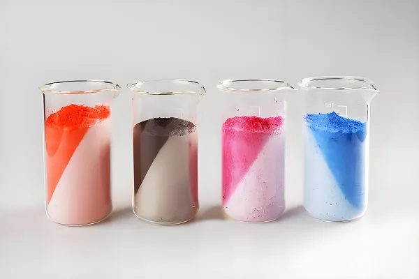
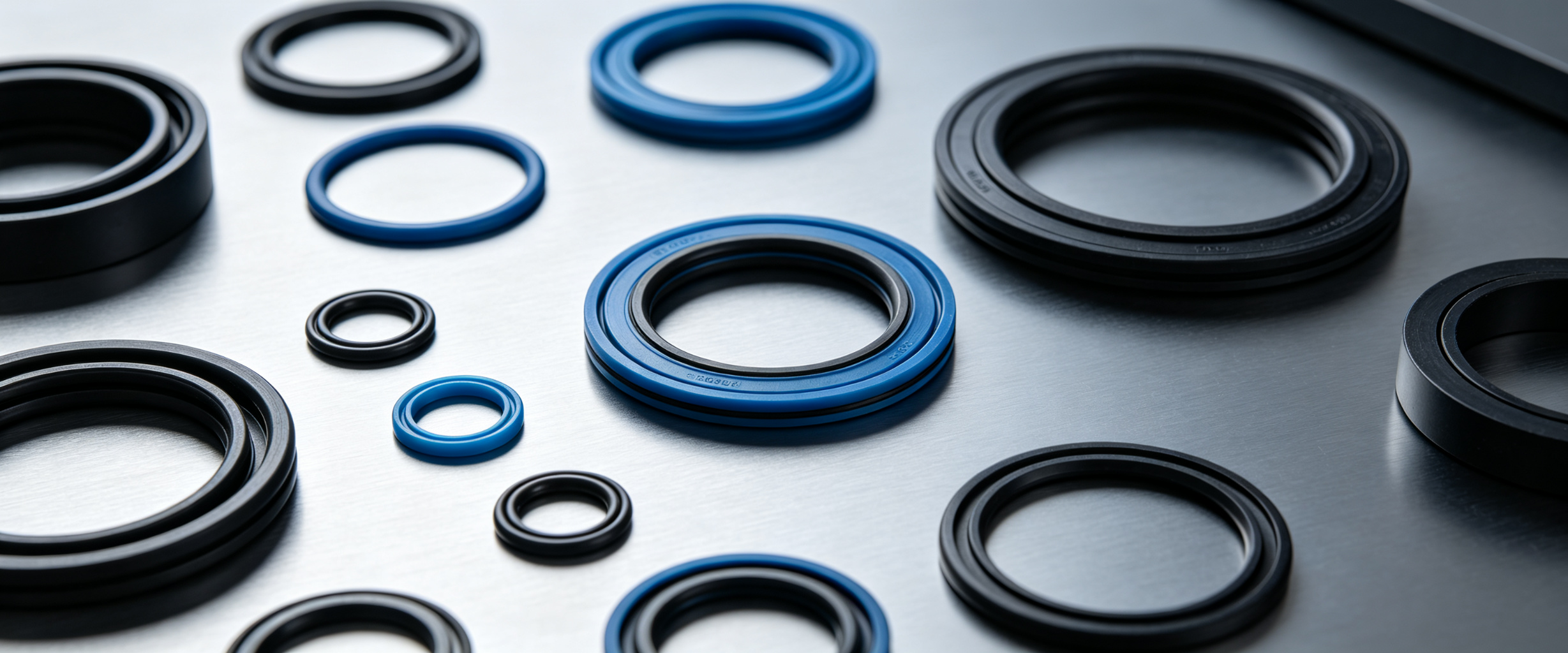
Rubber Seal Material Selection Guide
Choosing the correct elastomer material is critical for seal performance and service life. Each material offers unique properties for specific operating conditions.
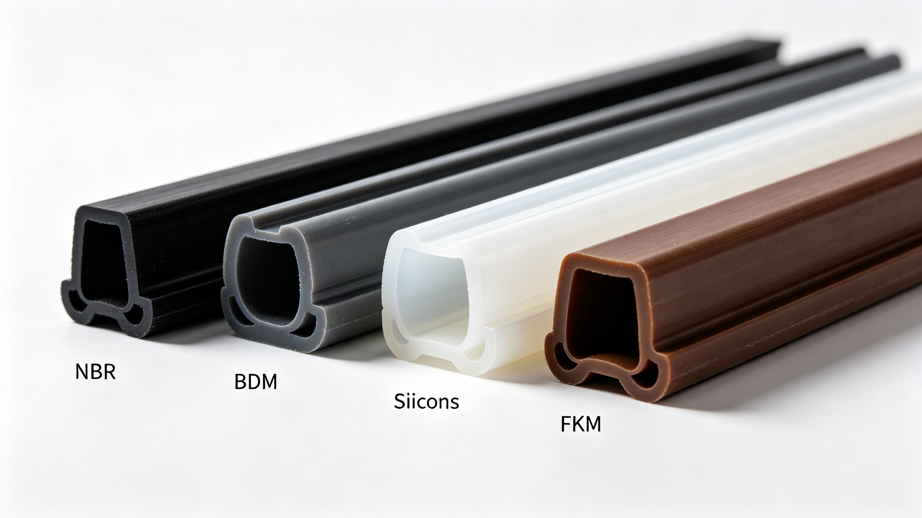
Common rubber seal materials: NBR, EPDM, Silicone, and FKM compounds
| Material | Oil Resistance | Chemical Resistance | Temperature Range | Primary Applications |
|---|---|---|---|---|
| NBR (Nitrile) | Excellent | Medium | -30°C to +120°C | Hydraulic Systems |
| EPDM | Poor | Excellent | -50°C to +150°C | Water & Outdoor |
| Silicone | Medium | Good | -60°C to +230°C | Medical & Food |
| FKM (Viton) | Excellent | Excellent | -20°C to +250°C | Chemical Processing |
| Neoprene | Good | Good | -40°C to +110°C | Marine Applications |
How to Choose the Right Rubber Seal
Follow this decision tree to quickly identify the optimal material for your specific application requirements.
Will the seal contact oil?
If your application involves hydraulic fluids, fuels, or lubricants:
✓ YES → Select NBR or FKM (Viton)
Will the seal contact chemicals?
For aggressive chemical environments or corrosive media:
✓ YES → Select FKM (Viton)
High temperature exposure?
For applications operating above 120°C continuously:
✓ YES → Select Silicone or FKM
Outdoor environment?
For UV exposure, ozone, weathering, and water resistance:
✓ YES → Select EPDM
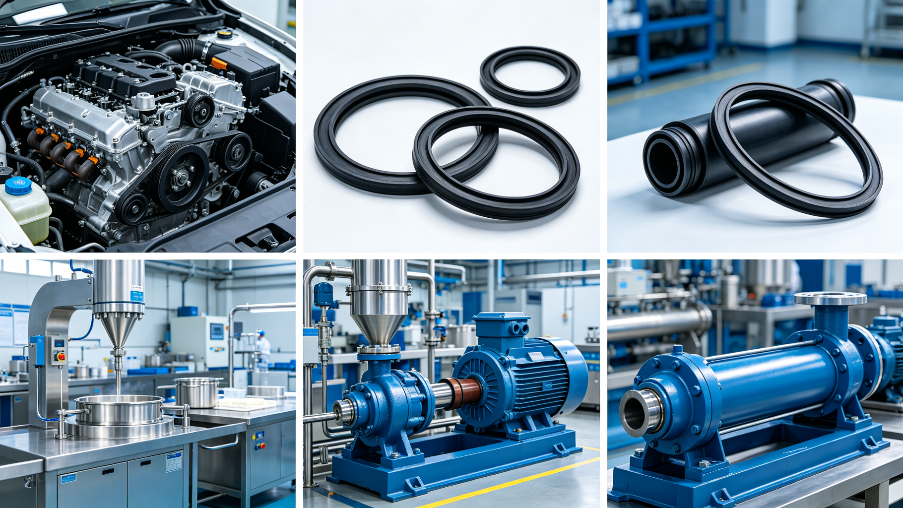
Rubber Seal Applications by Industry
Rubber seals serve critical functions across diverse industries, each with unique performance requirements and regulatory standards.
Automotive
- Brake System Seals
- Fuel System Components
- Cooling System Gaskets
- Engine Sealing Solutions
- Transmission Seals
Medical
- Diagnostic Equipment
- Fluid Transfer Systems
- Medical Device Seals
- Pharmaceutical Processing
- Biocompatible Materials
Food & Beverage
- Sanitary Equipment
- Pump & Valve Seals
- Processing Equipment
- FDA Compliant Materials
- Clean-in-Place Systems
Industrial Equipment
- Hydraulic Cylinders
- Pneumatic Systems
- Pump Seals
- Valve Stem Seals
- General Machinery
Marine
- Pump Seals
- Pipe Connections
- Hull Penetrations
- Deck Equipment
- Saltwater Resistance
Common Rubber Seal Failures and Solutions
Understanding failure modes is essential for proper seal selection and design. Below are the most common seal failure mechanisms and their proven solutions.
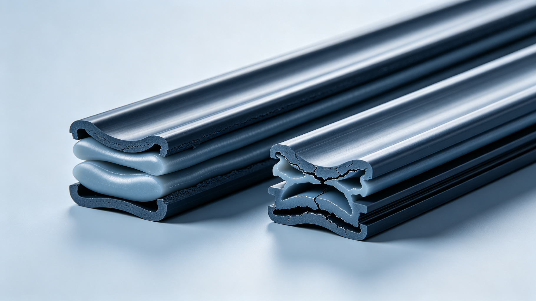
Proper material selection and design prevents premature seal failure
Rubber Seal Design Guidelines
Proper groove design and installation parameters are critical for seal performance. Follow these engineering specifications for optimal results.
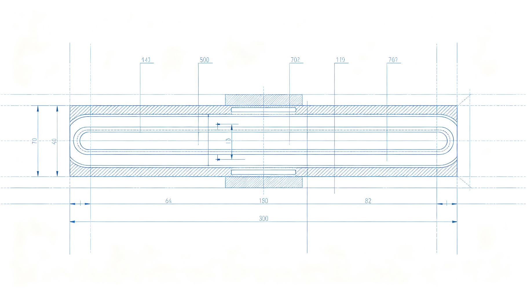
Technical cross-section diagram showing proper seal groove dimensions
Key Design Parameters
| Parameter | Recommended Range |
|---|---|
| Compression Ratio | 15–30% |
| Surface Finish | Ra 0.8–1.6 μm |
| Maximum Stretch | < 5% |
| Radial Clearance | 0.1–0.3 mm |
| Gland Fill | 70–90% |
Critical Installation Notes:
- Always deburr sharp edges and lead-in chamfers
- Use appropriate lubrication during assembly
- Avoid twisting or rolling seals during installation
- Verify tolerance stack-up before production
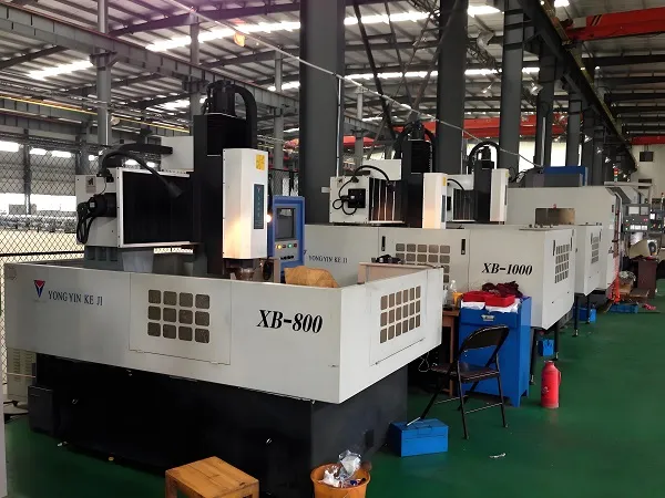
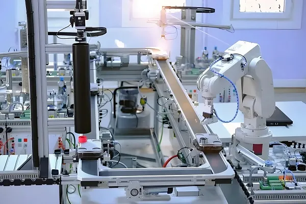
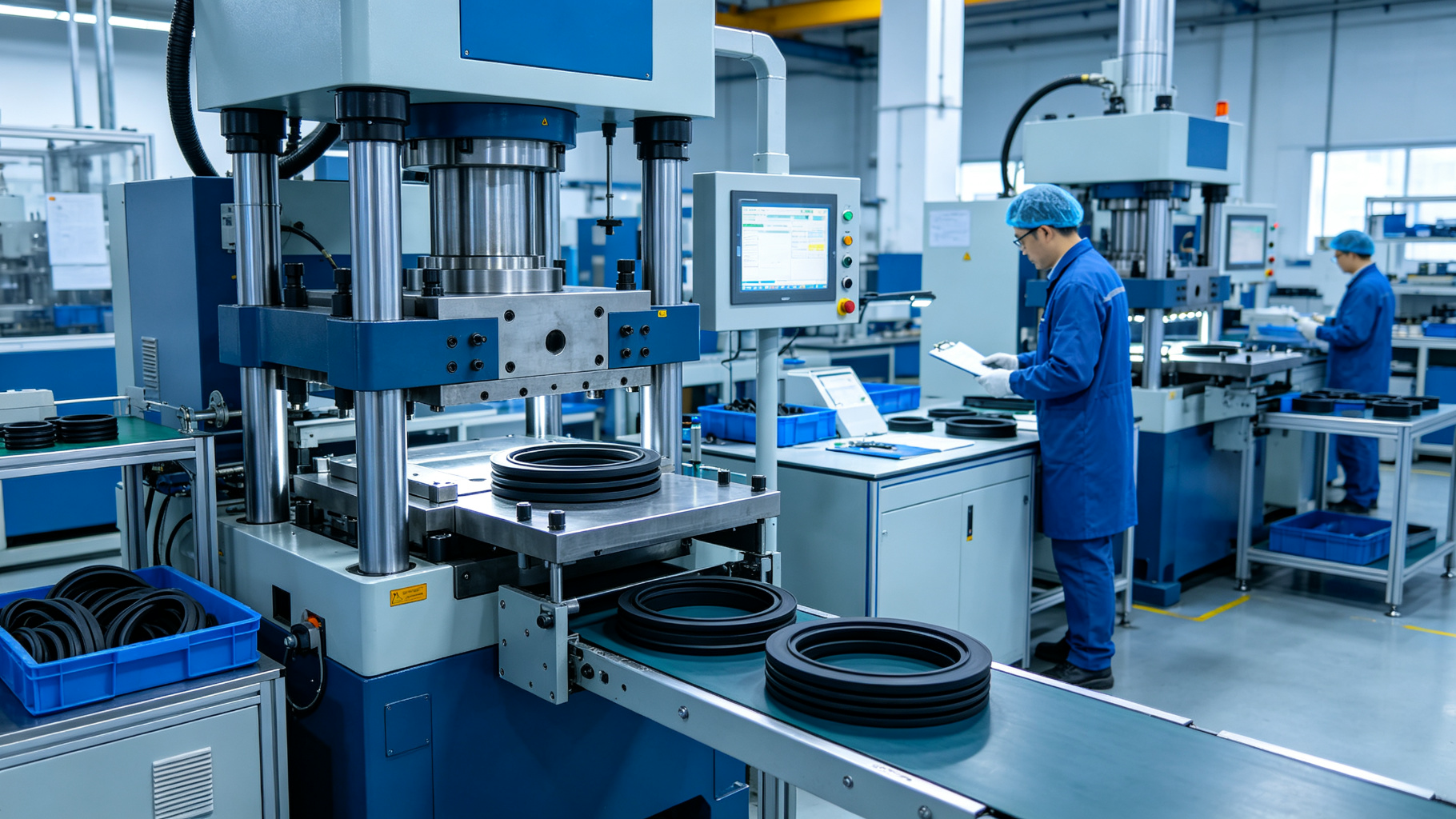
Manufacturing Process & Quality Control
At Xiamen Goldcattle, we employ advanced manufacturing technologies to produce precision rubber seals with consistent quality and performance.
Compression Molding
Ideal for low to medium volumes, complex geometries, and prototype development
Injection Molding
High-volume production with tight tolerances and excellent repeatability
Transfer Molding
Perfect for inserts, bonded assemblies, and medium production runs
Quality Inspection
Dimensional verification, material testing, and performance validation
Case Studies
Real-world sealing solutions from our engineering team
Hydraulic Cylinder Seal
Material: NBR 70 Shore A
Problem: Persistent oil leakage causing downtime
Solution: Redesigned groove geometry with optimized compression
Result: 100% leakage elimination achieved
Chemical Pump Seal
Material: FKM (Viton) 75 Shore A
Problem: Chemical attack causing rapid degradation
Solution: Material upgrade to specialty FKM compound
Result: Service life doubled from 6 to 12 months
Outdoor Equipment Seal
Material: EPDM 65 Shore A
Problem: UV cracking and ozone degradation
Solution: Weather-resistant EPDM formulation
Result: 5+ year outdoor durability verified
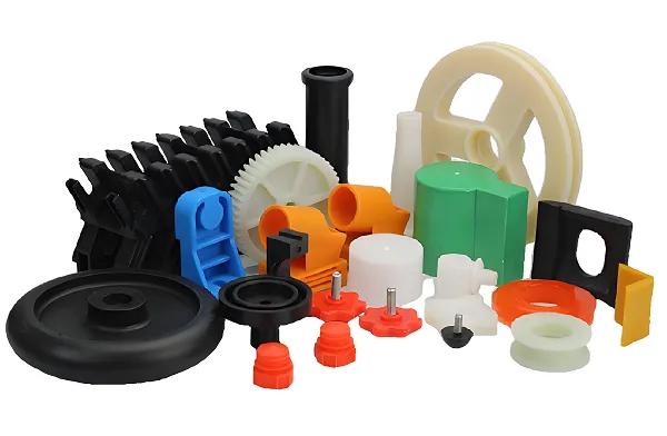
Custom Rubber Seal Manufacturing at Goldcattle
Xiamen Goldcattle Plastic & Metal Products Co., Ltd. provides comprehensive custom manufacturing solutions for rubber seals, CNC machined parts, and injection molded components.
Why Partner With Goldcattle?
One-stop custom manufacturing support for all your sealing and precision component needs
| Capability | Details |
|---|---|
| Material Options | NBR, EPDM, Silicone, FKM (Viton), Neoprene, Specialty Compounds |
| Production Methods | Compression Molding, Injection Molding, Transfer Molding |
| Order Volume | Prototype development through high-volume mass production |
| Tooling Support | In-house mold design, fabrication, and maintenance |
| Quality Inspection | Dimensional verification, material testing, performance validation |
| Industries Served | Automotive, Medical, Industrial, Marine, Aerospace |
Complete Manufacturing Ecosystem: Beyond rubber seals, Goldcattle offers integrated CNC machining, injection molding, and 3D printing services. This one-stop capability simplifies your supply chain and ensures consistent quality across all component types.
Questions Buyers Should Ask Before Ordering
Prepare these specifications when requesting a quotation to ensure accurate pricing and optimal seal performance.
Operating Temperature Range
Minimum and maximum continuous exposure temperatures
Media Compatibility
Specific fluids, chemicals, or gases the seal contacts
Pressure Requirements
System operating pressure and pressure cycling
Regulatory Requirements
FDA, NSF, USP Class VI, or industry-specific certifications
Expected Service Life
Target lifespan and maintenance intervals
Annual Usage Volume
Quantity requirements for optimal pricing
Tooling Requirements
Existing molds available or new tooling needed
Material Certifications
Material test reports, COC, or traceability documents
Rubber Seal Selection FAQ
What is the best material for oil resistance?
NBR (Nitrile Rubber) is the most cost-effective choice for general oil resistance. For harsh chemical environments or higher temperatures, FKM (Viton) provides superior performance and chemical compatibility.
EPDM vs NBR: Which should I choose?
Choose EPDM for outdoor applications, water exposure, and weather resistance. Choose NBR for oil, fuel, and hydraulic fluid applications. EPDM has poor oil resistance, while NBR has poor ozone/UV resistance.
What causes rubber seals to fail?
The most common failure modes are: compression set from prolonged load, swelling from fluid incompatibility, cracking from ozone/UV exposure, extrusion from high pressure, and thermal degradation from temperature extremes.
How long do industrial rubber seals last?
Service life varies dramatically based on application. Properly specified seals typically last 3-7 years in moderate conditions. Extreme temperatures, aggressive chemicals, or dynamic motion can reduce lifespan significantly.
Which seal material is best for chemicals?
FKM (Viton) offers the broadest chemical resistance for most industrial applications. For extremely aggressive chemicals or very high temperatures, specialty perfluoroelastomers (FFKM) may be required. Always verify compatibility with your specific media.
How do I design a proper sealing groove?
Follow industry standard groove dimensions: maintain 15-30% compression, Ra 0.8-1.6 surface finish, less than 5% installation stretch, and proper gland fill of 70-90%. Always include lead-in chamfers and deburr all sharp edges.