Engineering Practices from Material Formulation to Intelligent Manufacturing
Chapter 1: Materials Science and Product Characteristics
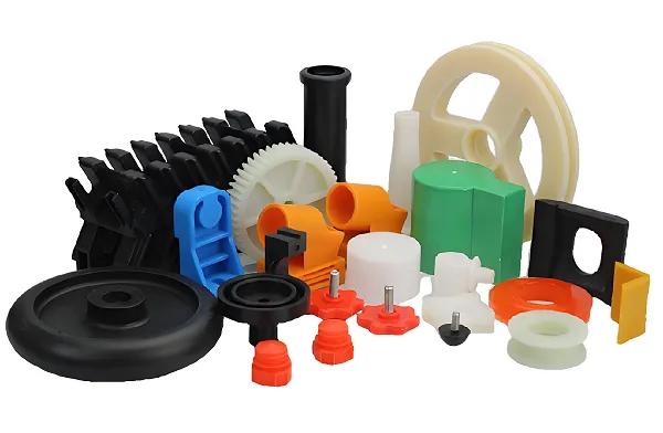
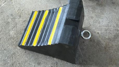
The performance core of rubber wheel chocks lies in the optimized design of polymer materials and composite modification technologies:
1.1 Material Systems and Functional Enhancement
- Base Materials:
- Natural Rubber (NR): With an elastic modulus of 1.5 – 3.0 MPa, it is suitable for conventional anti – slip scenarios.
- Styrene – Butadiene Rubber (SBR): The wear – resistant index is increased by 30%, and the tear resistance strength reaches 15 kN/m (ISO 34 – 1).
- Recycled Rubber: It is an environmentally friendly formula. The incorporation ratio is ≤ 40%, and the tensile strength retention rate is ≥ 85%.
- Reinforcement Technologies:
- Carbon Black Reinforcement: With an addition amount of 20 – 50 phr, the hardness is increased to 70 – 90 Shore A.
- Fiber Skeleton: Embedding a polyester fiber mesh can increase the tensile – breaking force to the 5 – ton level.
- Anti – aging Modification: Adding anti – UV agents and ozone inhibitors can extend the outdoor service life to more than 5 years.
1.2 Key Performance Parameters
| Parameter Category | Technical Indicators | Test Standards |
|---|---|---|
| Physical Dimensions | 270×180×120 mm (standard model) | ASTM D2240 |
| Static Friction | ≥ 0.6μ (dry road surface) | SAE J348 |
| Dynamic Load – bearing | Maximum 15 – ton single – axis load | ISO 9001 |
| Temperature Adaptability | – 40°C – + 80°C | MIL – STD – 810G |
Chapter 2: Processing Technology and Intelligent Manufacturing
The manufacturing of rubber wheel chocks integrates traditional vulcanization processes and digital production technologies:
2.1 Core Process Flow
plaintext
Mixing of Rubber Compounds → Pre - forming → Compression Vulcanization (150°C/15MPa) → Surface Treatment → Quality Inspection and Packaging
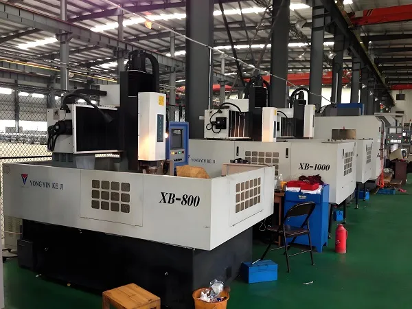
- Precision Mold Design: The mold cavity is processed by a five – axis machine, with a surface roughness Ra ≤ 0.8μm (process reference from web page 4).
- Intelligent Vulcanization Control: Using a PLC temperature control system, the vulcanization time error is ≤ ± 5 seconds.
- Surface Texture Treatment: Laser – engraved anti – slip patterns can increase the friction coefficient to 0.8μ (function extension from web page 2).
2.2 Special Process Options
- Fluorescent Marking: Adding long – afterglow materials can ensure a night – time visible distance of ≥ 50 meters.
- RFID Embedding: Implanting high – temperature – resistant chips to achieve digital asset management.
- Magnetic Base: Integrating neodymium – iron – boron magnets, with an adsorption force of ≥ 200N.
Chapter 3: Customized Solutions
In – depth adaptation solutions for different industry scenarios:
3.1 Industry Application Matrix
| Application Field | Customization Requirements | Technical Implementation Solutions |
|---|---|---|
| Aviation Ground Support | Resistance to aviation fuel corrosion | FKM fluororubber composite layer |
| Port Machinery | Resistance to salt – fog aging | EPDM rubber + galvanized steel core |
| Mining Equipment | Ultra – heavy load (30 tons +) | Multi – layer fiber – reinforced structure |
| New Energy Vehicles | Lightweight (weight ≤ 2kg) | Micro – foamed rubber technology |
3.2 Rapid Response Development System
plaintext
Requirement Collection → 3D Modeling (±1mm accuracy) → Material Formula Simulation → Prototype Trial - production → On - site Testing
- Digital Selection Platform: Input load, slope, and road surface type online to automatically generate product parameters.
- Modular Design: Supports customizations such as length extension (200 – 400mm) and height adjustment (± 20mm).
Chapter 4: Quality Control and Test Certification
4.1 Full – process Detection System
- Raw Material Detection: Control the Mooney viscosity (ML(1 + 4)@100°C: 45 – 65).
- Process Monitoring: Use X – ray to detect internal defects with a resolution of 0.1mm.
- Finished Product Testing:
- Slope Parking Test: Static hold on a 35° slope for ≥ 24 hours.
- Fatigue Test: 5000 dynamic impact cycles.
4.2 International Certification Standards
- Machinery Directive: Pass the EU 2006/42/EC certification.
- Environmental Standards: Comply with RoHS 3.0 and REACH regulations.
- Military Standards: Meet the special environmental requirements of MIL – C – 24162C.
Chapter 5: Industry Cutting – edge Development Trends
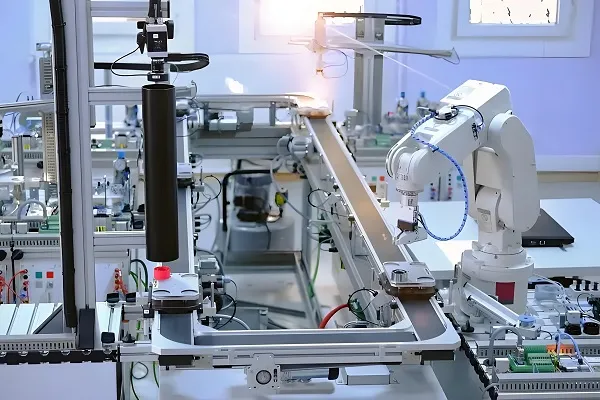
- Intelligent Integration:
- Embed pressure sensors to monitor the stress state of the wheel chock in real – time.
- Connect to the Internet of Things to achieve remote status monitoring.
- Sustainable Manufacturing:
- Application of bio – based rubber (natural rubber content ≥ 50%).
- Closed – loop recycling system with an old – part recovery rate of ≥ 90%.
- Multi – functional Composite:
- Liftable wheel chocks integrated with jack functions.
- Photovoltaic self – powered warning systems.
Conclusion
As the last line of defense in the vehicle safety parking system, modern rubber wheel chocks have evolved from simple wedges into intelligent safety devices. Driven by Industry 4.0 and carbon neutrality, wheel chock manufacturing is evolving towards digital customization and full – life – cycle management. Choosing a supplier with material research and development capabilities and intelligent production lines will be a key strategy for enterprises to improve the operational safety level.