Custom CNC Machined Automotive Driveshaft Components
Precision-machined shafts, spline ends, flange features and other drivetrain components manufactured to customer drawings, samples and application requirements — with material traceability, concentricity control and dimensional inspection.
What we supply, at a glance
| Manufacturing | CNC turning, CNC milling and 3 / 4 / 5-axis machining |
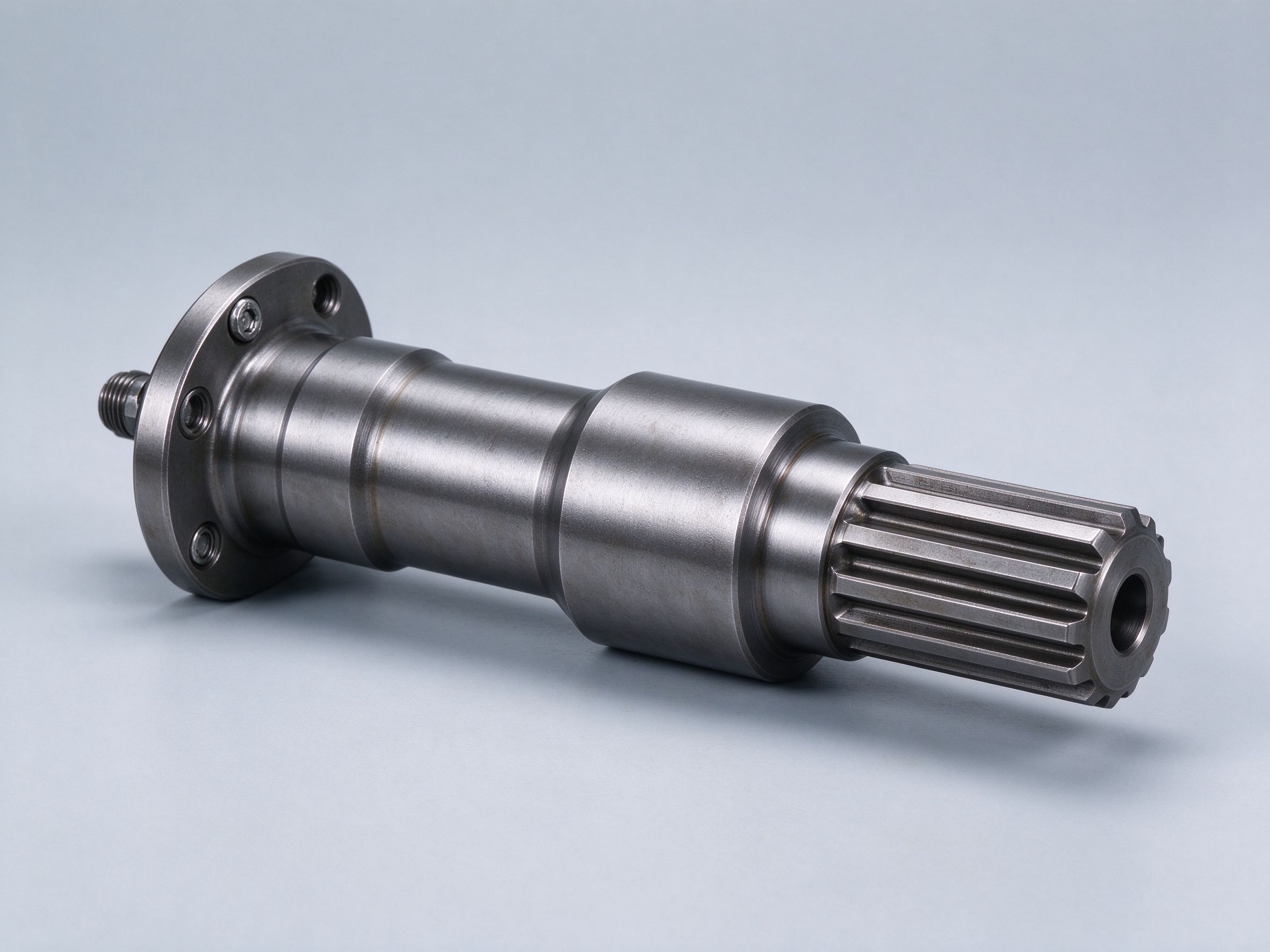
| Part types | Shaft bodies, stepped journals, splined ends, stub shafts, flange features, pins, sleeves and couplings |
| Materials | Alloy steel, carbon steel, stainless steel, aluminum — per drawing |
| Tolerance | Per drawing; CNC capability to ±0.005 mm on applicable features |
| Inspection | CMM and dimensional inspection against the drawing |
| Documentation | EN 10204 3.1 material certificate, dimensional report, CoC |
| Volume | Prototype → low-volume → repeat production |
| Input accepted | 2D drawing · 3D CAD · physical sample |
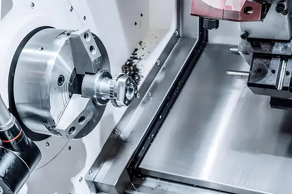
A CNC-machined automotive driveshaft component is a precision rotational part manufactured to transfer torque or connect drivetrain components. Depending on the design, critical features may include shaft diameters, spline profiles, flange interfaces, keyways, threads, concentricity and runout. Goldcattle machines custom metal drivetrain components from customer drawings, samples and CAD files using CNC turning, milling and multi-axis machining, with material traceability and dimensional inspection.
What automotive drivetrain components can we CNC machine?
We machine the metal components of the drivetrain, not a generic "driveshaft". Each part is defined by your drawing or sample — the categories below describe what our turning and multi-axis machines are set up to produce.
Shaft bodies & journals
Cylindrical shafts, stepped shafts, bearing journals and precision diameters.
Splined shafts
External and internal splines, machined to the specified profile, tooth form and fit class.
Stub shafts & ends
Shaft-end connection geometry, pinion and transmission-side interfaces.
Flange features
Bolted flange ends, mounting holes, dowel locations and register faces.
Yoke & coupling parts
Machined yoke-related and coupling components where the geometry is CNC-machinable.
Pins, sleeves & connectors
Precision dowels, spacers, sleeves and torque-transfer connectors.
Critical features in CNC-machined shaft components
For a rotating part, a nominal tolerance is not the whole specification. The features that determine whether a shaft fits, spins true and mates correctly are controlled individually against the drawing.
| Feature | Why it matters |
|---|---|
| Concentricity | Datum alignment between journals, bores and mating centers — the basis for balanced rotation. |
| Runout | Directly affects vibration, bearing life and seal performance at speed. |
| Diameter & bearing seats | Fit against bearings, seals and mating hubs; controlled to the drawing tolerance. |
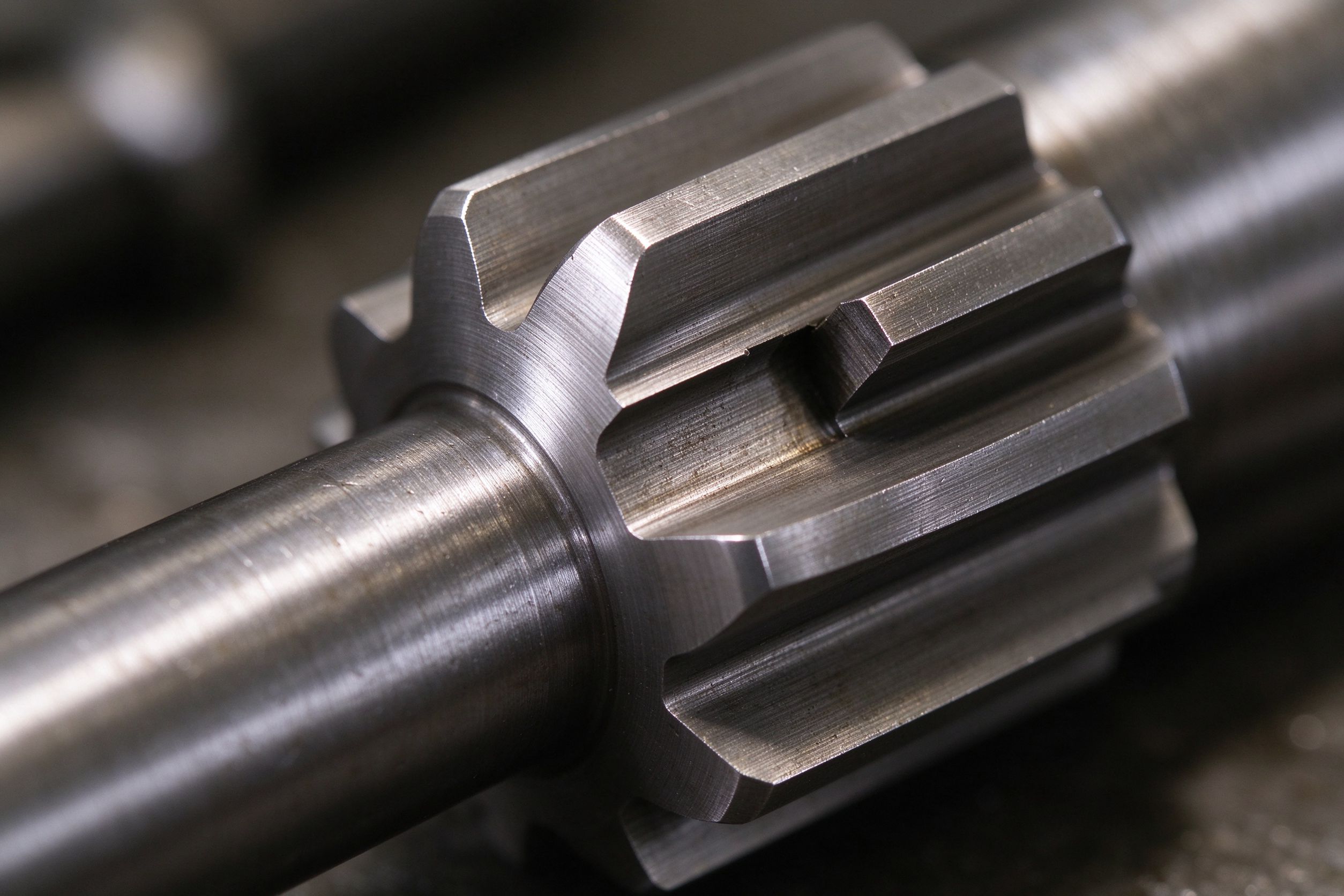
| Spline geometry | Torque transfer and mesh. Accuracy depends on the specified profile, tooth geometry, fit class and inspection method — not a single blanket number. |
| Keyways & grooves | Location and torque transfer to the mating component, defined by width, depth and position. |
| Threads | Standard, size, class and depth specified on the drawing; inspected with matching gauges. |
| Surface finish | Bearing and seal faces require a defined Ra; cosmetic or sealing surfaces are specified separately. |
Controlling concentricity, runout and spline mesh
Dimensional accuracy alone is not enough on a rotating component. We machine between centers where possible, use precision workholding, run in-process checks, and verify journals, bores and flange faces on the CMM — all referenced back to the drawing datum, not a nominal size.
For splines, we work from your specified profile and fit class. If you only have a sample, we can reverse-engineer the geometry and confirm it with you before cutting.
Materials for automotive shaft components
Materials are matched to the duty of the part. This page lists the steels and alloys we most often machine for drivetrain shafts — not a full material catalog.
4140 / 42CrMo4
The general high-strength shaft grade: good strength and toughness for loaded journals and flanges.
4340
Higher-strength applications where the duty demands it; confirmed against your requirement.
1045
Cost-effective general mechanical shafts and non-critical connection parts.
17-4 PH
Corrosion-resistant, high-strength niche applications.
6061 / 7075
Lightweight rotating and housing components, subject to load and fatigue review.
Coordinated, not assumed
Quench & temper, normalizing, carburizing, nitriding or induction hardening specified per grade and drawing, with supplier documentation where required.
Surface finishing for shaft components
Available finishes depend on material, application and drawing requirements — not an "everything on everything" list.
| Finish | Typical purpose |
|---|---|
| Black oxide | Corrosion resistance and appearance on steel parts. |
| Zinc plating | Corrosion protection for external steel surfaces. |
| Phosphate | Surface protection and a base for coating. |
| Passivation | Stainless steel corrosion resistance after machining. |
| Anodizing | Aluminum surface protection and appearance. |
| Grinding | Critical diameters and precise surface finish after heat treatment. |
| Polishing | Sealing faces or appearance surfaces. |
How a custom shaft component is made
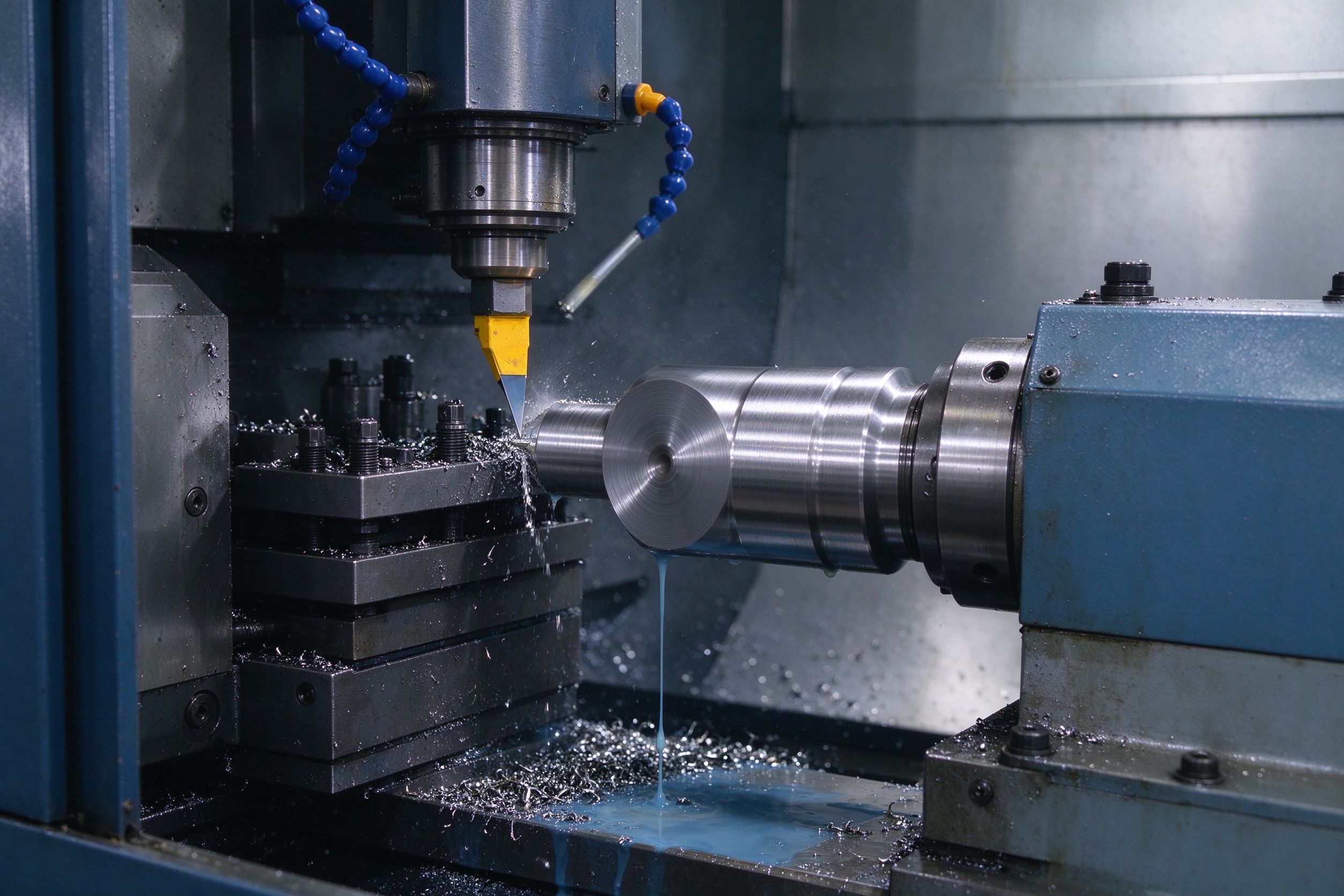
Shaft components follow a turning-first, milling-for-features, grind-for-critical-diameters route. The route is chosen per part rather than assumed.
When turning + milling are both needed
A shaft with a cylindrical body, shoulder, flange, bolt pattern, keyway, cross-hole or spline usually needs turning for the diameters plus milling or rotary-axis work for the non-round features. 5-axis is reserved for complex flange geometry, multiple angular features and parts where fewer setups protect face-to-face alignment — not assumed for every shaft.
What documentation you actually receive
Automotive buyers need evidence, not adjectives. Below is what we provide as standard, and what is available on request.
Standard with the order
Dimensional inspection report against your specified dimensions · Material certificate (EN 10204 3.1) · Certificate of Conformity · Surface treatment certificate where applicable.
Available on request
First Article Inspection (FAI) · PPAP support · control plan support · process capability data · heat-treatment report. Automotive-specific requirements are reviewed during RFQ.
MATERIAL TRACEABILITY
Manufactured under an ISO 9001:2015 quality system. Where a destination market or customer requires material declarations, REACH / ELV-related substance reporting or IMDS-style data, these can be prepared to the customer's specific requirement.
Complete driveshaft assemblies, or machined components?
We specialize in CNC-machined drivetrain components made to customer drawings and samples. Complete welded, phased and dynamically balanced driveshaft assemblies are undertaken only when the required joining, balancing and validation scope are confirmed for the specific project. If you need a finished, balanced assembly, tell us the scope in the RFQ and we will confirm what can be supported.
Typical applications and buyers
Drivetrain CNC parts are bought by different teams for different reasons. Each group usually cares about a different part of the specification.
Tier 1 / Tier 2
Repeatability, traceability, FAI / PPAP support and lot consistency.
Aftermarket brands
Fit, interchangeability, packaging and steady batch-to-batch quality.
Performance / racing
Custom geometry, strength and rotational performance in low volumes.
EV / new energy
Lightweight rotating parts, reduced mass and precision shaft features.
Engineering / prototype
One-off parts, fast DFM feedback and iteration before production.
What drives the cost of a custom shaft
| Factor | Effect |
|---|---|
| Material grade | Raw material cost |
| Diameter / length | Material plus machine time |
| Spline complexity | Programming and tooling |
| Number of setups | Setup time |
| Tolerance | Inspection and process control |
| Heat treatment | External processing and distortion control |
| Grinding | Added precision process |
| Quantity | Unit cost falls at volume |
CNC machining vs forging or casting
| Method | Best suited for |
|---|---|
| CNC machining | Prototypes, low-to-medium volume, complex precision features. |
| Forging + machining | High-strength structural parts at larger production volumes. |
| Casting + machining | Near-net-shape parts when production economics justify it. |
The right process depends on annual volume, material, geometry, mechanical requirements and tooling economics. For prototype and low-volume precision shaft work, CNC is usually the most direct route.
Alloy-steel stepped shaft with spline and flange
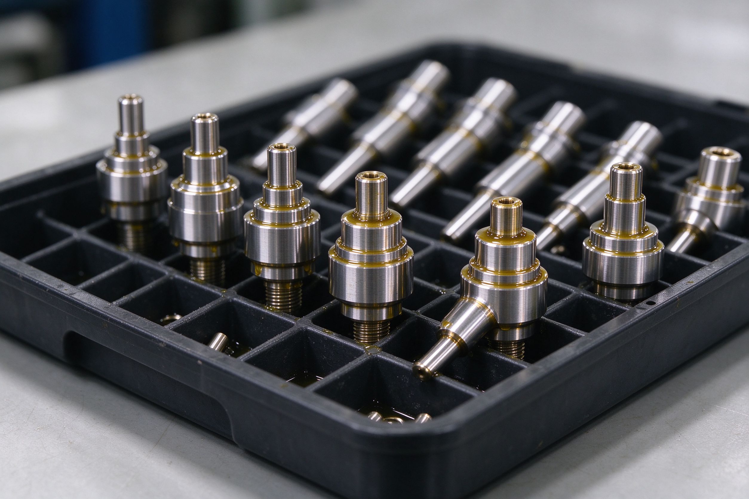
Pilot batch, 8 pcs
- Component
- Stepped shaft with splined end and bolted flange
- Material
- 42CrMo4 (4140 class), stress-relieved
- Critical
- Concentricity between bearing journals and splined bore; runout at flange face
- Process
- CNC turning + 4-axis milling, then finish-grind journals
- Inspection
- CMM on journals, bore and flange face; dimensional report
- Documentation
- EN 10204 3.1 material certificate per batch
- Outcome
- Journals and spline mated on first fit; part moved to repeat pilot batch on the same route.
Project profile shown is representative of a typical pilot order. Specific dimensions, quantities and results are confirmed per RFQ and not stated as blanket process averages.
What to send for a quote
The more of this you provide, the faster and more accurate the quote — and the fewer assumptions we make about critical features.
Minimum for a shaft component
2D drawing · 3D CAD (STEP / IGES / X_T) · material grade · heat-treatment requirement · quantity · critical tolerances · spline specification · surface finish · inspection requirements.
For an assembly or high-speed part
Overall length · joint type · spline count and series · tube diameter and wall · operating RPM · torque requirement · balance requirement · phasing requirement.
Frequently asked questions
Do you make complete driveshaft assemblies, or only machined components?
Can you machine a driveshaft component from a physical sample?
Can you make splined shafts and internal splines?
How do you control concentricity and runout?
Can you provide material certificates?
Can you support PPAP or First Article Inspection?
Do you coordinate heat treatment?
What is the prototype minimum order?
Request a custom automotive shaft quote
Send your 2D drawing, 3D CAD file or existing sample. Tell us the material, quantity, critical tolerances, spline and inspection requirements — our engineering team reviews manufacturability before the quote is issued.
Related: CNC turning for shafts · 5-axis CNC machining · tight-tolerance machining · custom CNC services