Answer:
CNC machining, namely Computer Numerical Control machining, is mainly based on three key aspects: numerical control equipment, machining programs, and machining processes. Numerical control equipment serves as the hardware foundation of CNC machining, such as CNC lathes, CNC milling machines, etc. Machining programs are the instruction sets that control the operation of the equipment, usually written through specialized programming software. Machining processes are the technological specifications that determine machining methods, machining sequences, tool selection, etc., ensuring the production of parts that meet requirements.
Extended Knowledge Points:
As an extremely important machining method in modern manufacturing, the basic knowledge of CNC machining covers multiple dimensions. The following will be introduced in – depth from various aspects.
I. Core Concepts and Development History of CNC Machining
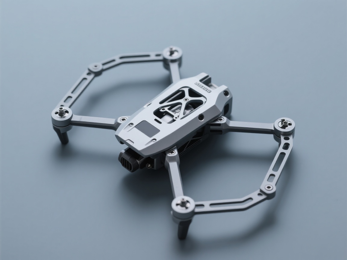
CNC machining is a method of controlling mechanical motion and the machining process using digital information. Its core lies in precisely controlling the moving parts of the machine tool, such as the rotation of the spindle and the movement of the worktable, through computer programs, thus achieving high – precision and high – efficiency part machining. Its development has gone through several stages, from simple numerical control in the early days to the highly intelligent and integrated computer numerical control today. With the continuous progress of computer technology, sensor technology, and automation technology, the accuracy, speed, and degree of automation of CNC machining have been greatly improved, and it is widely used in many fields such as aerospace, automotive manufacturing, electronic equipment, and medical devices.
II. CNC Machining Equipment
Equipment Types
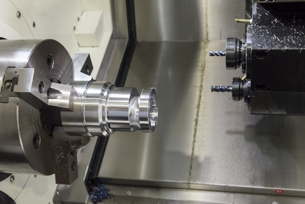
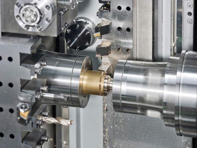
CNC Lathe: It is mainly used for processing rotary parts such as shafts and discs. The spindle drives the workpiece to rotate, and the tool moves along the X and Z axes to perform machining operations such as turning outer circles, inner holes, and threads. It is widely used in the processing of automobile engine crankshafts and various shaft – type parts.
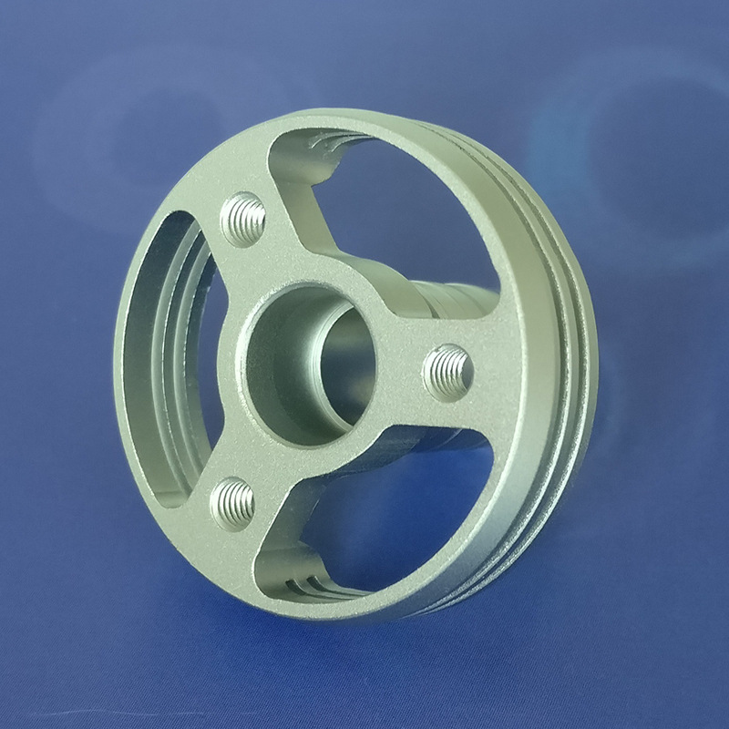
CNC Milling Machine: It can perform various machining tasks such as planar milling, contour milling, and cavity machining. It can process complex 2D and 3D part shapes and plays a key role in mold manufacturing and mechanical part processing. The tool can move along the three coordinate axes of X, Y, and Z. Some high – end CNC milling machines are also equipped with rotating axes to achieve four – axis and five – axis linkage machining, further expanding the processing capabilities.
Machining Center: Based on the CNC milling machine, it is equipped with a tool magazine and an automatic tool – changing device. It can complete multiple machining processes such as milling, drilling, boring, and tapping in one clamping, greatly improving processing efficiency and accuracy and reducing workpiece clamping errors. It is often used for the comprehensive processing of complex parts.
CNC Grinding Machine: It is used for grinding the surface of parts to obtain high – dimensional accuracy and surface finish and is indispensable in the fields of precision part processing and mold processing.
Equipment Composition
Machine Tool Body: It is the basic structure of CNC machining equipment, including the bed, column, worktable, etc., providing a stable support and movement platform for processing. The structural design and manufacturing quality of the machine tool body directly affect the rigidity, accuracy, and stability of the machine tool.
Numerical Control System: It is the “brain” of CNC machining equipment. It receives and processes machining programs, converts the instructions in the programs into control signals for the moving parts of the machine tool, and controls parameters such as the movement trajectory, speed, and spindle speed of the machine tool. Common numerical control systems include FANUC, SIEMENS, Huazhong CNC, etc.
Servo Drive System: According to the control signals sent by the numerical control system, it accurately controls the movement of each axis of the machine tool. It consists of a servo motor, driver, and feedback device. The feedback device real – time detects the speed and position of the motor and feeds the information back to the numerical control system to achieve closed – loop control and ensure processing accuracy.
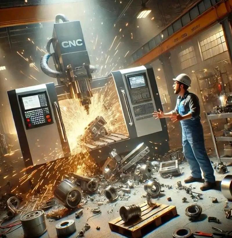
Auxiliary Devices: These include the cooling system, lubrication system, chip – removal device, protective device, etc. The cooling system is used to reduce the cutting temperature, improve tool life, and machining surface quality. The lubrication system ensures good lubrication of the moving parts of the machine tool and reduces wear. The chip – removal device timely removes the chips generated during processing to prevent chip accumulation from affecting processing. The protective device ensures the safety of operators and the normal operation of the machine tool.
III. CNC Machining Programs
Programming Basics
Programming Languages: Commonly used CNC programming codes include G – codes (preparatory function codes) and M – codes (auxiliary function codes). G – codes are used to specify the movement mode of the machine tool, coordinate system, tool compensation, etc. For example, G00 represents rapid positioning, and G01 represents linear interpolation. M – codes are used to control the auxiliary actions of the machine tool, such as M03 represents the spindle rotating clockwise, M05 represents the spindle stopping, M08 represents the coolant on, and M09 represents the coolant off.
Programming Methods: There are mainly two methods: manual programming and automatic programming. Manual programming is when the programmer manually writes the machining program according to the requirements of the part drawing, following certain rules and formats. It is suitable for the processing of parts with simple shapes and fewer program segments. Automatic programming uses computer – aided design and manufacturing (CAD/CAM) software, such as UG, Mastercam, SolidWorks, etc. First, perform 3D modeling of the part, then automatically generate the machining program through the machining module of the software, and then post – process it into the code that the machine tool can recognize. Automatic programming is highly efficient and suitable for the programming of complex parts.
Programming Process
Analyze the Part Drawing: Clearly understand the shape, dimensions, accuracy requirements, surface roughness, and other technical requirements of the part, and determine the machining process and machining route.
Determine the Machining Process: Select appropriate machining methods, tools, cutting parameters, etc. For example, for hole machining, select suitable drills, reamers, or boring tools according to the diameter, depth, and accuracy requirements of the hole, and determine reasonable cutting speeds and feed rates.
Establish the Workpiece Coordinate System: When programming, a workpiece coordinate system needs to be established to convert the dimensions on the part drawing into programming coordinates. Usually, the reference point on the part is selected as the origin of the workpiece coordinate system.
Write the Machining Program: According to the machining process and the workpiece coordinate system, use the programming language to write the machining program. In the program, accurately specify parameters such as the tool movement trajectory, spindle speed, and feed rate.
Program Verification and Simulation: Before the written program is officially input into the machine tool for processing, it needs to be verified and simulated. The correctness of the program can be checked through the graphic simulation function of the numerical control system or professional simulation software. Observe whether the tool movement trajectory is reasonable and whether there are problems such as interference and collision.
Program Transmission and Processing: Transmit the verified program to the numerical control system of the machine tool through a USB flash drive, network, etc., and perform trial – cutting processing. Adjust the program appropriately according to the trial – cutting results until a qualified part is processed.
IV. CNC Machining Processes
Machining Process Planning
Part Analysis: Conduct a comprehensive analysis of the part’s structure, material, and technical requirements, understand the processing difficulties and key points of the part, and provide a basis for formulating the machining process. For example, for materials with high hardness, select appropriate tool materials and cutting parameters; for thin – walled parts, consider the deformation problem during processing.
Determine the Machining Method: Select appropriate machining methods according to the shape and accuracy requirements of the part. For example, planar machining can use methods such as milling, planing, and grinding; hole machining can use methods such as drilling, reaming, boring, and boring.
Divide the Machining Stages: Generally, the machining process of a part is divided into roughing, semi – finishing, and finishing stages. Roughing mainly removes most of the machining allowance to improve processing efficiency; semi – finishing prepares for finishing to ensure a certain machining accuracy and surface quality; finishing achieves the final dimensional accuracy and surface roughness requirements of the part.
Arrange the Machining Sequence: Arrange the machining sequence following the principles of roughing first and then finishing, main surfaces first and then secondary surfaces, and planes first and then holes. For example, first machine the reference surface of the part, and then machine other surfaces with the reference surface as the positioning reference; first machine the main surfaces, and then machine the secondary surfaces.
Tool Selection and Determination of Cutting Parameters
Tool Selection: Select appropriate tools according to factors such as machining methods, part materials, and machining accuracy. For example, end – mills or face – mills can be selected for milling planes; twist drills can be selected for drilling holes; taps and dies can be selected for thread processing. The tool material is also very crucial. Common tool materials include high – speed steel, carbide, ceramics, etc., and different materials are suitable for different machining conditions.
Determination of Cutting Parameters: Cutting parameters include cutting speed, feed rate, and depth of cut. The cutting speed affects tool wear and processing efficiency; the feed rate affects the machining surface quality; and the depth of cut is related to the machining allowance. Reasonable selection of cutting parameters requires comprehensive consideration of factors such as part materials, tool materials, and processing equipment, and determination through consulting cutting manuals or practical experience.
The basic knowledge of CNC machining involves multiple aspects such as equipment, programming, and processes, which are interrelated and mutually influential. Only by comprehensively mastering this basic knowledge and continuously accumulating experience in practice can one proficiently apply CNC machining technology, process high – quality parts, and meet the growing needs of modern manufacturing.
The above content comprehensively analyzes the basic knowledge of CNC machining. If you have any questions about a certain part or want to know more in – depth application cases, please feel free to let me know.