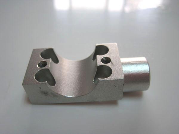
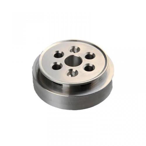
Aluminum prototype machining refers to the process of rapidly manufacturing product prototype parts using aluminum alloys as raw materials through CNC milling, turning, or five-axis machining. Its core is transforming 3D design models into processing instructions to drive machine tools to remove materials from aluminum blocks, forming prototypes with high precision and specific properties. Commonly used aluminum alloys include 6061, 7075, 5052, etc., which are suitable for prototype verification in aerospace, automotive, electronics, and other fields due to their light weight, high strength, and good machinability. Machined parts can enhance corrosion resistance and appearance through surface treatments like anodizing and electroplating, with precision up to ±0.05mm. They can be directly used for functional testing, assembly verification, or appearance review, accelerating product development iteration.

I. Technical Principles and Machining Characteristics of Aluminum Alloys
1. Technical Advantages of Aluminum Alloys
- Physical Properties: Density of about 2.7g/cm³ (1/3 that of steel), tensile strength reaching 310-570MPa (e.g., 7075-T6 aluminum alloy), combining light weight and high strength;
- Machining Characteristics: High thermal conductivity (205W/m·K) facilitates heat dissipation during cutting, but adhesive tooling must be prevented in high-speed machining;
- Surface Treatment Adaptability: Anodizing forms a 0.5-25μm oxide film, significantly improving wear resistance—a key technical advantage distinguishing aluminum prototypes from other materials.
2. Key Points of CNC Machining Technology
- Tool Selection: Use cemented carbide (e.g., YG6) or PCD tools; edge sharpness should adapt to aluminum’s ductility to avoid cutting burrs;
- Cutting Parameters:
- Milling 6061 aluminum alloy: spindle speed 10,000-15,000rpm, feed rate 800-1200mm/min, cutting depth ≤2mm;
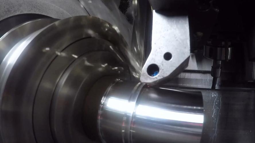
- Turning 7075 aluminum alloy: linear speed controlled at 150-250m/min to prevent tool wear from work hardening.
II. Analysis of the Complete Process Flow
1. Preprocessing Technology
- Material Preprocessing:
- Stress Relief: Anneal 7075 plates (350℃×2h) to avoid machining deformation;
- Blank Preparation: Reserve 1-3mm machining allowance according to part size; large aluminum blocks are cut by sawing or waterjet.
- Process Planning:
- Thin-walled parts machining: Adopt “multiple layered cutting” strategy, e.g., 0.5mm wall thickness shell cut in 5 layers, 0.2mm allowance each time;
- Complex structures: Use five-axis 联动 machining for impeller-like parts, achieving blade surface forming through angular milling.
2. Cutting Execution Process
- Rough Machining: Use large-diameter end mills (φ10-20mm) for rapid roughing, leaving 0.5-1mm finishing allowance; select emulsion coolant to prevent adhesive tooling;
- Finishing Machining:
- Mirror finishing: Use diamond-coated tools, feed rate ≤0.05mm/r, surface roughness up to Ra≤0.4μm;
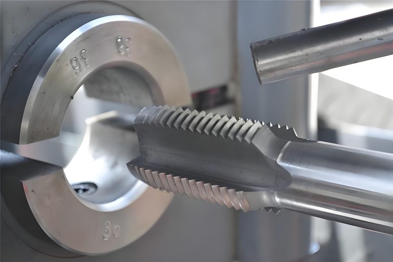
- Thread machining: When tapping M3 fine-pitch threads, use special aluminum taps with cutting oil lubrication to prevent tap breakage.
3. Post-Processing Technology
- Surface Treatment:
- Anodizing: Sulfuric acid anodizing forms a transparent oxide film (5-10μm thickness); hard anodizing (25-50μm) for wear-resistant parts;
- Electroplating: Electroless nickel plating (5-10μm thickness) improves salt spray resistance (≥500 hours);
- Deburring: Vibratory finishing or electrolytic deburring to ensure no residual burrs on precision mating surfaces (e.g., threaded holes).
III. Technical Terms and Concepts
| Term | Definition and Application in Aluminum Machining |
|---|---|
| Tool Coating | TiAlN coating for aluminum machining reduces friction coefficient to 0.3, tripling tool life |
| Cutting Heat Management | 70% of cutting heat in aluminum machining is carried away by chips; control chip discharge speed to prevent winding |
| Aging Treatment | 7075 aluminum alloy requires artificial aging (120℃×24h) after machining to stabilize dimensional accuracy |
| Minimum Cutting Thickness | Minimum 0.01mm cutting in aluminum micro-machining, suitable for electronic connector prototypes |
| Intergranular Corrosion | Untreated 2024 aluminum alloy is prone to intergranular corrosion in humid environments, requiring anodizing protection |
IV. Aluminum Prototype Machining Processes and Part Characteristics
1. Machining Capabilities and Technical Limitations
- Complex Structure Machining:
- Five-axis machining enables deep cavity machining (depth-diameter ratio >10:1) of aluminum aerospace engine casings, with tool paths avoiding interference;
- Micro-milling technology can machine 0.1mm-wide aluminum heat sinks with tool diameters ≤0.5mm;
- Deformation Control:
- Thin-walled aluminum parts (wall thickness <0.3mm) use vacuum adsorption fixtures to reduce clamping deformation;
- Large aluminum frames (e.g., automotive battery casings) require zoned cutting, releasing stress after each zone before continuing.
2. Typical Aluminum Alloys and Part Matching
| Alloy Grade | Mechanical Properties | Typical Part Application Scenarios |
|---|---|---|
| 6061-T6 | Tensile strength 310MPa, elongation 12% | Automotive suspension bracket prototypes, UAV frames |
| 7075-T6 | Tensile strength 570MPa, hardness 150HB | High-strength aerospace connectors, racing wheel prototypes |
| 5052-H32 | Tensile strength 210MPa, excellent corrosion resistance | Marine component prototypes, chemical equipment casings |
| 2024-T3 | Tensile strength 470MPa, easy to machine | Electronic device casings, model engine parts |
V. Industry Applications and Verification Scenarios of Aluminum Prototype Parts
1. Functional Verification Scenarios
- Automotive Field:
- Aluminum alloy engine cylinder head prototype: Machined φ45mm valve hole with cylindricity ≤0.01mm for combustion efficiency testing;
- New energy battery casing prototype: Verified sealing performance through hydrostatic test (10MPa), lightweight design reducing weight by 30%;
- Aerospace:
- Aluminum alloy wing connector prototype: Fatigue test (10^7 cycles) verifies strength, dimensional tolerance ±0.03mm;
- Satellite antenna bracket prototype: Tested for dimensional stability through high-low temperature cycles (-50℃~+120℃).
2. Appearance and Assembly Verification
- Consumer Electronics:
- Mobile phone middle frame prototype: 7075 aluminum alloy milled into 0.5mm ultra-thin frame via CNC, anodized to match mass-produced models;
- Laptop cooling module prototype: Aluminum extruded heat sink with 0.8mm fin spacing, heat dissipation efficiency test ≥90%;
- Medical Devices:
- Surgical instrument handle prototype: 6061 aluminum alloy with hard anodized surface, roughness Ra≤0.2μm, meeting medical-grade cleanliness requirements.
Conclusion
Aluminum prototype machining relies on the lightweight, high toughness, and excellent machinability of aluminum alloys to achieve high-precision prototype manufacturing through CNC technology. From high-strength aerospace connectors to ultra-thin consumer electronics casings, its technical core lies in optimizing cutting processes using aluminum alloy properties and expanding application boundaries through surface treatments. In product development, aluminum prototype parts not only verify structural strength and functional performance but also simulate mass-production states through material properties, serving as a key bridge between design and manufacturing.

