Updated: January 23, 2026 | Author: Zhang Gong, Goldcattle Surface Finish Expert (15+ years experience)
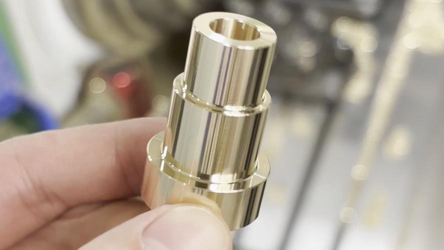
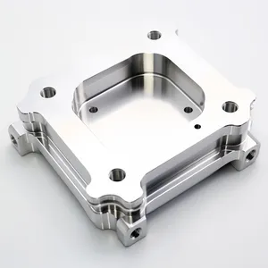
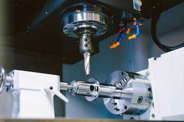
Example of a high-quality CNC machined component with Ra 0.8μm finish
Let’s Be Real – Surface Finish Matters!
Bro, if your CNC parts look like they’ve been through a sandstorm, you’re gonna have problems. Bad surface finish isn’t just ugly – it messes with friction, sealing, corrosion resistance, and even how long parts last. I’ve seen so many shops waste time and money because they didn’t get this right!
The good news? You can fix most surface finish issues by picking the right tools, tweaking cutting parameters, using better coolant, and handling materials properly. Let’s dive in!
1. Tool Selection – The Foundation of Good Finish
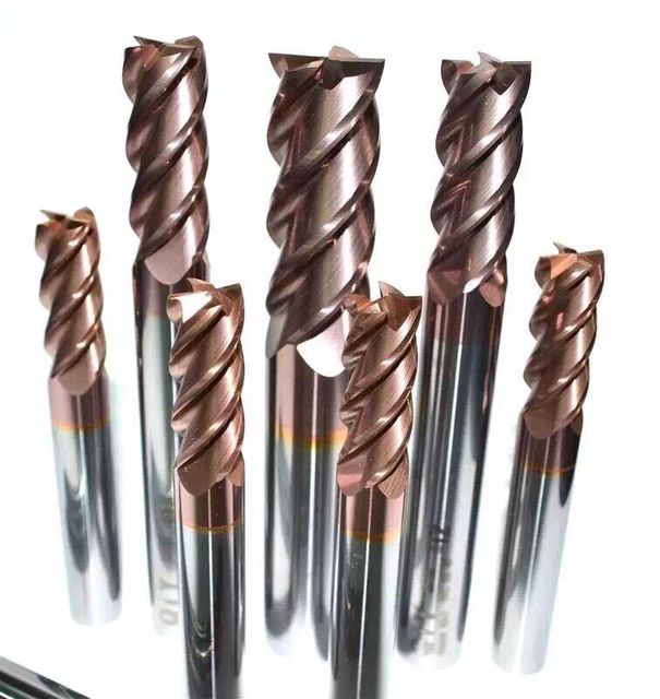
High-performance carbide end mills with various coatings for different materials
Tool Materials & Coatings – Game Changers!
- Carbide Tools: Dude, these are way better than HSS for hard stuff like steel and titanium. With TiAlN or AlCrN coatings, they reduce heat and friction like crazy. I’ve gotten Ra 0.8-1.6μm on steel parts with these – perfect for hydraulic components that need to seal tight!
- Diamond Tools: For aluminum and brass? PCD tools are the GOAT! They can get Ra <0.05μm – that’s mirror smooth, bro. Great for smartphone frames or any optical parts where looks matter.
- Tool Geometry: Sharp cutting edges (5-10° relief angle) and polished flutes prevent material tearing. Ball-nose mills with big radii (10-20mm) make curved surfaces way smoother – I’m talking <0.005mm scallop height!
- Tool Maintenance: Dull tools = garbage finish! Replace them when edge rounding hits 0.02mm. I once forgot to do this on medical parts and had to scrap 50 surgical instrument handles – not fun!
2. Cutting Parameters – Tweak These for Perfection
Test Data (For Reference Only!)
| Material | Spindle Speed | Feed Rate | Resulting Ra |
|---|---|---|---|
| Aluminum 6061 | 15,000-30,000 RPM | 0.02 mm/rev | 0.4-0.8μm |
| Steel 4140 | 8,000-15,000 RPM | 0.03 mm/rev | 0.8-1.6μm |
| Titanium | 6,000-10,000 RPM | 0.03 mm/rev | 1.2-2.0μm |
*These are just examples – always test with your specific setup!
Spindle Speed – Faster Isn’t Always Better!
For aluminum, 15k-30k RPM gives great finish, but go below 3k RPM and you’ll get BUE (built-up edge) that leaves the surface looking like a cheese grater. Trust me, I’ve seen it!
Feed Rate – Slow Down for Smoothness
0.01-0.05 mm/rev for finishing works best. I once ran a 10mm carbide end mill at 0.02 mm/rev on brass and got Ra 0.8μm – beautiful! But at 0.1 mm/rev? Ra jumped to 3.2μm – yikes!
Cutting Depth – Light Passes = Happy Parts
0.1-0.3mm finish passes prevent distortion. I had a job with 0.5mm aluminum brackets – a 0.1mm finish cut removed all the roughing marks without causing vibration chatter.
Real-World Example
We had an aerospace client needing Ra 0.4μm on fuel injectors. We used 5-axis machining with PCD tools at 220 m/min, 0.04 mm/rev, and 80 bar coolant. Result? Ra 0.36μm average – they were stoked!
3. Coolant & Chip Evacuation – Don’t Ignore This!
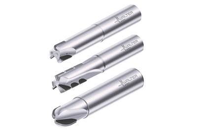
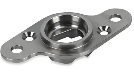
Specialized milling cutters with chip breakers for better surface finish
Coolant Types – Pick the Right One!
- Flood Cooling: 70-100 bar pressure flushes chips and cools tools. Use oil-based for steel, water-soluble (5-10%) for aluminum. I once forgot to change coolant for 3 months – bad idea, chips were sticking everywhere!
- Mist Cooling: Perfect for titanium! The fine mist gets into deep slots and holes, preventing chip entanglement that scratches surfaces.
- Chip Breaking: Tools with chip breakers turn long chips into small pieces. I tested this on brass – 35° rake angle insert gave Ra 0.8μm vs. Ra 2.0μm with a straight insert. Night and day difference!
4. Material-Specific Tips – Different Materials = Different Approaches
Metals – The Most Common Stuff
- Aluminum & Brass: Soft and sticky! Use sharp tools, high speeds, and lots of coolant. For mirror finish (Ra <0.02μm), follow with vibratory polishing for 1-2 hours. I did this for a jewelry client – they couldn’t believe how shiny the parts were!
- Steel & Titanium: Hard and tough! Coated carbide tools and moderate speeds work best. Abrasive flow machining (AFM) can get internal surfaces to Ra 0.05μm – perfect for hydraulic valve bores.
Plastics & Composites – Tricky But Doable
- ABS & PC: Melts easily! Keep spindle speed low (3k-5k RPM) and use uncoated carbide tools. For matte finish (Ra 1.6μm), light sanding with 400-grit paper works great.
- CFRP (Carbon Fiber): Fibers fray like crazy! PCD tools with negative rake angles (5-10°) and low feeds (0.01-0.03 mm/rev) shear fibers cleanly. I got Ra 1.6μm for aerospace panels – the client was thrilled!
5. Surface Finish Standards – Know What You’re Aiming For
Common Industry Standards
SPI Finish Standard (Plastics Industry)
- A1/A2: Super high gloss (diamond buffing) – Ra <0.05μm
- B1/B3: Semi-fine (stone polishing) – Ra 0.1-0.4μm
- C1/C3: Commercial (standard machining) – Ra 0.8-3.2μm
Industry-Specific Requirements
- Aerospace: Ra <0.4μm (fuel injectors)
- Medical: Ra <0.02μm (surgical tools)
- Automotive: Ra 0.8-1.6μm (transmission gears)
- Electronics: Ra <0.1μm (connector pins)
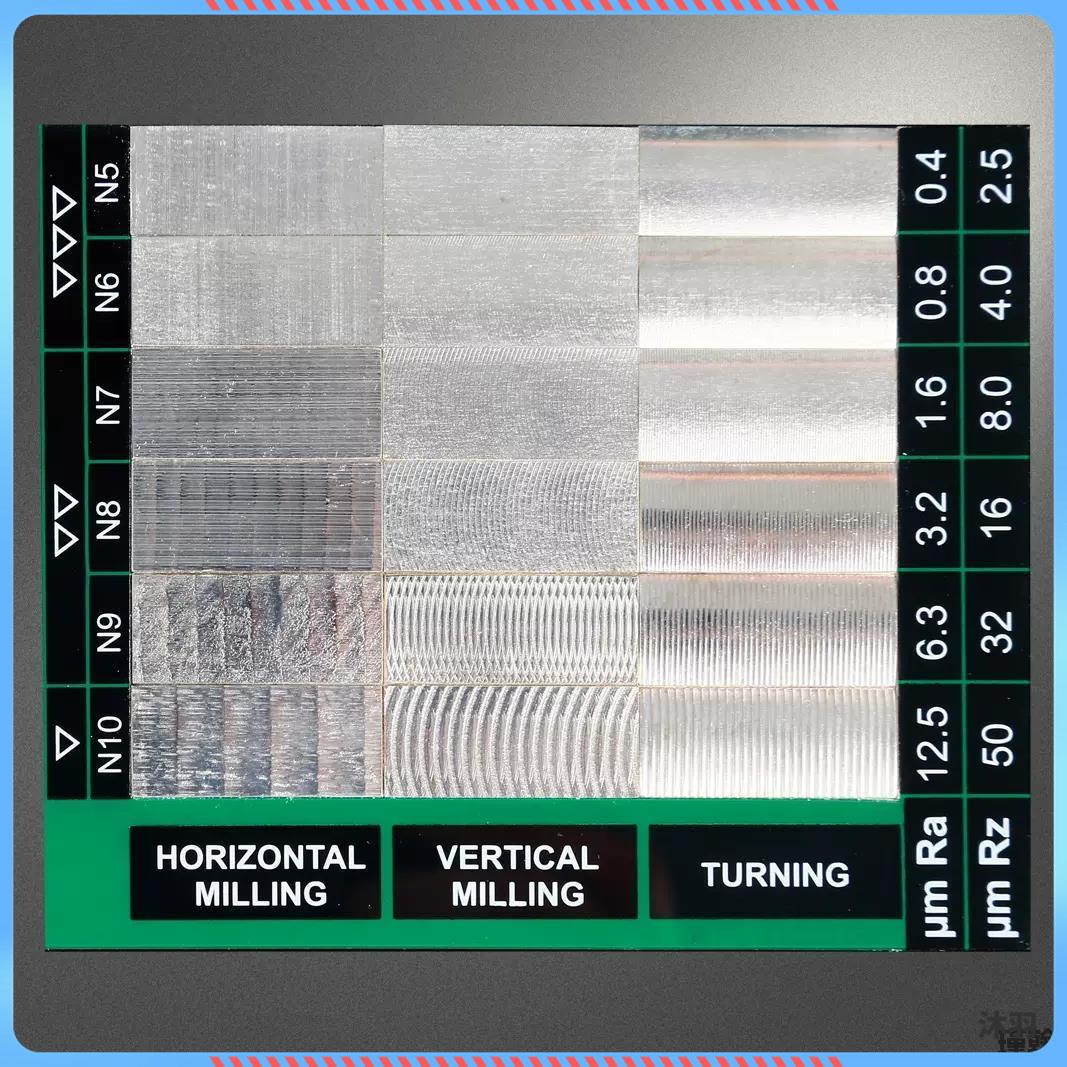
Surface roughness comparison chart showing different Ra values for various machining processes
6. Troubleshooting – Fixing Common Problems
Chatter Marks – The Vibration Monster
These wavy lines are from tool vibration. Fix it by:
- Increasing spindle speed
- Using shorter tool overhangs (I went from 50mm to 25mm on a 10mm end mill – problem solved!)
- Adding damping fixtures
Built-Up Edge (BUE) – The Sticky Nightmare
When material sticks to the tool. Fix it by:
- Using more coolant
- Sharpening tools
- Increasing speed (I bumped aluminum from 5k to 20k RPM – BUE vanished!)
Scratches – The Chip Problem
From loose chips or dirty coolant. Fix it by:
- Using high-pressure coolant to flush chips
- Filtering coolant to 5μm
- Cleaning the machine regularly (I learned this the hard way after scratching 20 parts!)
7. 2026 Trends – What’s Next in Surface Finish?
- AI Real-Time Monitoring: Systems that adjust parameters on the fly – we tested this and got 20% better Ra consistency!
- Sustainable Cooling: Bio-based coolants that reduce carbon footprint by 30% – good for the planet and your finish!
- Nano-Level Finishes: Demand for Ra <0.01μm is growing 45% annually (medical and aerospace)
- EU/US New Standards: Stricter regulations on surface quality for critical components – stay ahead of the curve!
Real-World Success Story (2025 Aerospace Client)
We had an aerospace client needing Ra 0.4μm on turbine blades. By optimizing tool paths, using PCD tools at 220 m/min, and implementing real-time vibration monitoring, we got Ra down to 0.36μm – and reduced production time by 15%! They’ve been a repeat client ever since.