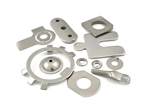
Rules of thumb for metal stamping are practical guidelines simplifying design and process decisions, focusing on formability, geometry, and efficiency. Key examples include using a minimum bend radius of 1× material thickness, ensuring hole diameters ≥ material thickness, and limiting draw depth to 3× diameter for deep drawing. These rules balance manufacturability, cost, and part quality across materials and applications.
Detailed Analysis of Key Rules of Thumb for Metal Stamping
1. Material & Formability Guidelines
These rules ensure materials are compatible with stamping operations, preventing cracks, tears, or excessive wear:
-
Minimum Bend Radius = 1× Material Thickness (T)
For ductile materials (mild steel, aluminum 3003), the inner bend radius should be at least the material thickness (e.g., 1mm radius for 1mm thick steel). This avoids overstretching outer fibers, which cause cracking. Brittle materials (high-carbon steel, titanium) require larger radii (2×T to 3×T) to accommodate lower ductility. For example, bending 2mm thick stainless steel needs a 4mm radius to prevent edge fractures. -
Avoid Tight Inside Corners in Drawing
When deep drawing (shaping hollow parts), inside corners should have radii ≥0.5×T to ensure smooth material flow. Sharp corners (radius <0.25×T) create stress concentrations, leading to thinning or tearing. A 3mm thick aluminum can, for instance, requires a minimum corner radius of 1.5mm to maintain uniform wall thickness during drawing. -
Material Thickness Consistency
Stamping performs best with uniform material thickness (±0.05mm tolerance). Avoid abrupt thickness changes (e.g., a 1mm section adjacent to a 3mm section) as they cause uneven stress distribution, leading to warping or wrinkling. If thickness variation is necessary, transition gradually over 5×T to distribute strain.
2. Hole & Feature Design Rules
These guidelines optimize the creation of holes, slots, and cutouts, preventing tool damage and ensuring part integrity:
-
Hole Diameter ≥ Material Thickness
Piercing holes smaller than the material thickness risks tool breakage and produces ragged edges. A 2mm thick steel sheet requires holes ≥2mm in diameter; a 1mm hole in this sheet would overload the punch, causing premature wear or failure. For small holes (<T), use laser cutting first, then stamp secondary features. -
Hole Distance from Edges ≥ 1.5×T
Holes too close to part edges weaken the material, leading to tearing during stamping. A 1.5×T gap (e.g., 3mm for 2mm thick aluminum) ensures sufficient material to withstand punch force. This rule is critical for structural parts like brackets, where edge strength prevents failure under load. -
Slot Length ≤ 5× Width
Long, narrow slots (length >5× width) are prone to bending or distortion during piercing. A slot 1mm wide should not exceed 5mm in length; longer slots require multiple punches or stepped designs to distribute cutting force evenly. This avoids tool deflection and ensures straight, clean edges.
3. Press & Tooling Guidelines
These rules optimize equipment use, reducing tool wear and improving process efficiency:
-
Press Tonnage = 3× Material Thickness × Perimeter of Cut
A quick formula for estimating required press force: multiply the material thickness (in mm) by the total perimeter of cuts/features (in mm) and by 3 (a safety factor). For example, blanking a 100mm × 50mm mild steel part (2mm thick) has a perimeter of 300mm, requiring 3×2×300 = 1,800 kgf (≈18 tons) of force. This prevents underpowered presses from producing incomplete cuts or damaging dies. -
Die Clearance = 5–10% of Material Thickness
The gap between punch and die (clearance) should be 5% of T for soft materials (aluminum) and 10% for hard materials (steel). A 2mm thick steel part needs 0.2mm clearance (10% of 2mm) to ensure clean shearing without burrs. Too little clearance causes tool rubbing; too much leaves ragged edges. -
Tool Life: 100,000 Strokes for Mild Steel
Standard tool steel dies (H13) last ~100,000 strokes when stamping mild steel. For harder materials (stainless steel), expect 30–50% shorter life; for softer materials (aluminum), life extends to 200,000+ strokes. Regular maintenance (polishing, regrinding) preserves tool life, ensuring consistent part quality.
4. High-Volume & Complex Part Rules
For mass production and intricate geometries, these rules minimize defects and reduce costs:
-
Progressive Die Stations: 1 Operation per Station
In progressive stamping (high-volume production), each die station should perform one operation (piercing, bending, blanking) to avoid overcomplicating tooling. This simplifies setup, reduces jams, and improves consistency. A part requiring 4 features (2 holes, 1 bend, 1 blank) needs 4 stations, with 2×T spacing between stations to prevent interference. -
Draw Ratio ≤ 3:1 for Deep Drawing
The maximum depth of a drawn part (height) should not exceed 3× its diameter to avoid excessive thinning. A cup with a 50mm diameter can safely reach 150mm in height; deeper cups require multi-stage drawing with annealing between steps to relieve work hardening. This prevents necking (localized thinning) and ensures uniform wall thickness. -
Avoid Undercuts in High-Volume Stamping
Undercuts (recessed features) require complex, expensive dies with retractable punches. For high-volume parts, redesign undercuts as external flanges or use post-stamping operations (e.g., machining) if necessary. This reduces tooling costs and speeds up production cycles.
5. Industry-Specific Adaptations
Rules of thumb adjust to sector-specific needs, balancing functionality and manufacturability:
-
Automotive Stamping
Body panels use a minimum bend radius of 0.8×T to balance aesthetics and formability. Hole distances from edges are increased to 2×T for crashworthiness, ensuring parts withstand impact without fracturing. -
Electronics Stamping
Micro-components (0.1–0.5mm thick) require tighter die clearances (3% of T) to maintain precision. Hole diameters are often limited to ≥0.5×T for copper contacts, ensuring electrical conductivity isn’t compromised by material deformation. -
Aerospace Stamping
Titanium parts use 2×T bend radii and reduced press speeds (50% of steel) to avoid cracking. Draw ratios are limited to 2:1 for high-strength alloys, prioritizing structural integrity over part height.
These rules of thumb distill decades of stamping expertise, providing quick, reliable guidance for designers and manufacturers. While they don’t replace detailed engineering analysis, they prevent common pitfalls, reduce trial-and-error, and ensure parts are both functional and cost-effective to produce across industries.