Die Casting Mold Core Design & Manufacturing Guide for Complex Internal Geometries
Complex internal geometries require specialized core design to ensure part quality, dimensional accuracy, and long tool life. This guide explains how precision core design works, what capabilities to look for in a supplier, and how we deliver reliable multi-directional core solutions for OEM projects.
What Is a Mold Core in Die Casting?
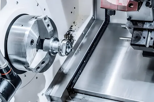
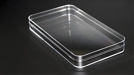
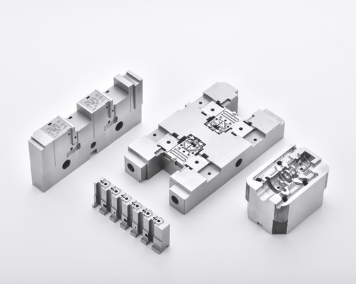
A die casting mold core is a precision-machined insert that forms the internal features of a cast part — including holes, cavities, channels, and recesses — that cannot be created by the mold cavity alone. The core typically sits on the moving half of the die and retracts during ejection to release the part.
The core must withstand repeated exposure to molten metal at 380–700°C and injection pressures up to 15,000 psi. Core materials are predominantly H13 hot-work tool steel, typically hardened to 48–52 HRC for die casting applications. For parts with internal side features, the core requires a core-pulling mechanism (hydraulic or mechanical) to retract the core before ejection.
In summary, the mold core is the most technically demanding component in die casting tooling — it defines the part’s internal geometry and directly determines quality outcomes for porosity, dimensional accuracy, and mechanical integrity.
When Is a Complex Mold Core Required?
A mold core is not just about creating a through-hole. Complex core designs are required when the part contains internal features that cannot be formed by the mold cavity alone:
| Application Scenario | Technical Challenge | Buyer Evaluation Focus |
|---|---|---|
| Multi-directional internal channels | Requires multiple cores at different angles | Supplier’s multi-axis core pulling capability |
| Side holes / undercuts | Core must retract sideways before mold opens | Whether the supplier uses hydraulic or mechanical slides |
| Deep cavities (depth/diameter > 3:1) | Core deflection risk, heat concentration | Coolant channel design inside the core |
| Thin-walled internal structures (<2mm) | Filling difficulty, premature solidification | Mold flow simulation experience |
Our engineering team handles cores up to 300mm depth with multi-directional pulling, supporting parts with internal complexity that many suppliers decline.
The key factor in determining whether a complex core is needed is whether the internal feature can be formed by the mold parting line alone — if not, a movable core and pulling mechanism are mandatory.
Core Design & Manufacturing Process
DFM Analysis of Internal Geometry
Before cutting steel, our team reviews your 3D model, analyzes internal features, and delivers a DFM report with optimization suggestions within 24-48 hours, using CAD/CAM and mold flow simulation.
Core Structure Design & Simulation
We design cores for strength and thermal balance, with mold flow simulation to validate filling, solidification, and shrinkage compensation (1.2% for aluminum) before machining.
Core Pulling System Design
For off-axis features, we design hydraulic or mechanical core pulling mechanisms, supporting up to 5-direction independent pulling for complex geometries.
Material Selection & Heat Treatment
We use H13 hot-work tool steel, with heat treatment per NADCA #207 standards, hardening to 48-52 HRC with optional vacuum treatment and nitriding.
Precision Machining (CNC + EDM)
5-axis CNC for roughing, EDM for intricate details, achieving ±0.01mm standard tolerance, ±0.005mm with jig grinding, and Ra 0.4μm surface finish.
Assembly & Mold Trial
Full assembly and trial on our 160T-2000T die casting machines, with full dimensional and quality validation, achieving 95% first trial pass rate.
Core Design Principles — What Determines a Reliable Core
✔ Core Strength & Deflection Prevention
During injection at 1,000–15,000 psi, molten metal exerts enormous force on the core. We control depth/diameter ratio, add core support pins, and use FEA analysis to prevent deflection, wall thickness variation, or core breakage.
✔ Ventilation & Gas Venting Design
Trapped gas is the #1 cause of porosity in internal cavities. We design 0.05-0.1mm vent grooves, overflow wells, and optional vacuum assist to eliminate trapped gas, ensuring porosity-free internal features.
✔ Draft Angle & Ejection Design
Without proper draft angles (1–3° for internal surfaces), the core will drag and gall during ejection. We design internal draft angles larger than external surfaces, with precision ejection system fit to prevent damage.
✔ Thermal Expansion & Shrinkage Compensation
Cores heat to 380–700°C during casting. We precisely account for thermal expansion and material shrinkage — 1.2% for aluminum, with different values for zinc and magnesium — to ensure final part dimensions are within tolerance.
✔ Mold Life & Maintenance
Core inserts are wear components with a finite service life. We design cores as replaceable inserts that can be individually swapped without dismantling the entire mold, reducing downtime and long-term maintenance costs for your production line.
The key factor in core reliability is not any single design element — it is the systematic integration of strength, thermal management, venting, and ejection into one coherent engineering solution.
Core Defects, Root Causes & Prevention
| Defect | Root Cause | Prevention Strategy |
|---|---|---|
| Porosity | Insufficient venting; gas trapped in deep cavities | Add vent grooves; optimize overflow design; vacuum assist |
| Core breakage | Excessive thermal stress; insufficient structural strength | Optimize core geometry; proper H13 heat treatment per NADCA #207 |
| Misalignment | Loose core fit; wear on sliding surfaces | Precision grinding to ±0.005mm on mating surfaces; regular inspection |
| Shrink porosity | Inadequate feeding during solidification | Optimize gating and riser design; mold flow simulation verification |
| Cracking (Hot tear) | Uneven cooling; abrupt section changes | Uniform cooling channel layout; gradual transitions in core geometry |
For every core we manufacture, we conduct pre-production mold flow analysis to identify potential defect locations before machining begins. This eliminates costly rework and ensures first-article quality.
Core Pulling Mechanism Explained
When a part requires internal features in directions other than the mold opening direction, a core pulling mechanism (also known as a slide or side-action) is mandatory. This is one of the clearest indicators of a supplier’s technical capability — not all die casting suppliers can execute multi-directional core pulling.
Mechanical Core Pulling (Angled Pin)
- Uses mold opening/closing force to drive the angled pin and slide
- Best for: Simple side holes/undercuts, short pull distances
- Advantage: Low cost, no external power equipment needed
- Limitation: Limited pull force and pull distance
Hydraulic Core Pulling
- Independent hydraulic cylinder drives the core/slide movement
- Best for: Deep holes, high locking force, multi-directional pulling
- Advantage: High pull force, independent control from mold cycle
- Our capability: Support up to 5-direction independent hydraulic pulling
The ability to design and execute hydraulic core pulling separates production-grade suppliers from limited-capability workshops. Multi-directional hydraulic core pulling is a standard requirement for automotive housings, aerospace brackets, and complex medical device components.
Core Materials & Heat Treatment Standards
The choice of core material and heat treatment specification directly affects tool life, dimensional stability, and per-part cost. For aluminum die casting, the industry standard is H13 hot-work tool steel, selected for its high-temperature strength and resistance to thermal fatigue.
| Material | Standard | Typical Hardness | Application |
|---|---|---|---|
| H13 (4Cr5MoSiV1) | NADCA #207 / GB/T1299 | 48–52 HRC | Aluminum die casting cores |
| 1.2344 (DIN) | DIN EN ISO 4957 | 48–52 HRC | European equivalent of H13 |
| SKD61 (JIS) | JIS G4404 | 48–52 HRC | Japanese standard |
Heat Treatment Process (NADCA Compliant)
- Quenching: 1020–1050°C, air/oil cooling
- Double tempering: 530–620°C, eliminating residual stress
- Optional nitriding: Enhance surface hardness, extend tool life
- Premium option: DIEVAR or premium H13 with vacuum heat treatment for extended life
Case Study — Complex Multi-Core Housing Project
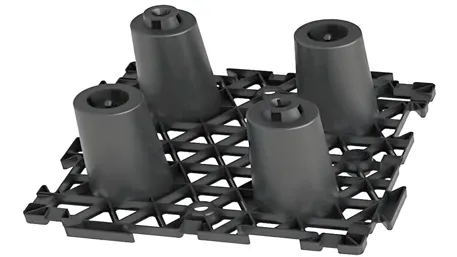
Project: Aluminum Alloy Automotive Electronic Controller Housing
Challenge: The part featured internal channels in three directions and a deep undercut requiring side-core pulling — geometry that multiple local suppliers declined to quote.
Our Solution: We designed a mold with three hydraulic core pulling units — one for each direction of the internal channels. Core cooling channels were embedded to ensure uniform temperature distribution during casting, verified via mold flow simulation.
Project Results:
- Core alignment achieved: ±0.02mm positional accuracy
- Porosity rate: ≤2% in critical internal areas (validated by X-ray inspection)
- Tool life: exceeded 500,000 shots with no core replacement required
- Part quality: passed customer’s full PPAP submission on first trial
This project demonstrates our ability to design and manufacture complex multi-core molds that many suppliers cannot handle — and to deliver production-ready quality on the first mold trial.
Why Our Core Design Reduces Failure Risk
Choosing a die casting supplier for complex core work involves significant technical risk. Here’s how we reduce that risk:
Pre-production Simulation
Mold flow analysis before machining
NADCA Compliant
Heat treatment per NADCA #207
Precision Machining
±0.01mm standard, ±0.005mm achievable
Full Inspection
CMM + X-ray inspection reports
Fast DFM Feedback
DFM report within 24–48 hours
PPAP Support
Full production part approval
In summary, reducing failure risk in complex core manufacturing requires engineering depth — not just machining capability. Our integrated approach from DFM through mold trial ensures that your mold core performs reliably from shot one.
Frequently Asked Questions
What is a die casting mold core?
A die casting mold core is a movable or fixed steel insert that forms internal cavities, holes, and recesses in a cast part. It is the component that shapes the inside of the casting — everything the cavity cannot form.
How do you design a core for complex internal cavities?
Complex internal cavities require multi-directional core design with hydraulic or mechanical core pulling. The design process starts with a DFM review to identify the optimal number of cores, pulling directions, and cooling layout — followed by mold flow simulation to verify filling and solidification before machining.
What materials are used for die casting mold cores?
The industry standard core material is H13 hot-work tool steel (also specified as 1.2344 or SKD61), hardened to 48–52 HRC through quenching at 1020–1050°C and double tempering at 530–620°C per NADCA standards.
What is core pulling in die casting?
Core pulling is a mechanism that retracts a core from the cast part before ejection. It is required whenever internal features (side holes, undercuts) cannot be released by the mold opening direction alone. Options include mechanical (angled pin) for simple applications and hydraulic for complex or multi-directional pulling.
How do you prevent porosity in core-formed cavities?
Porosity in internal cavities is prevented through a combination of proper core venting (vent grooves or porous inserts), optimized gating design, and — for critical applications — vacuum assist during casting. Mold flow simulation identifies at-risk areas before production.
What tolerances can be achieved with precision core machining?
Standard CNC machining achieves ±0.01mm on core dimensions. With jig grinding or high-precision EDM, tolerances can be tightened to ±0.005mm for critical features.
How long does it take to manufacture a complex die casting mold core?
A complete mold with complex cores typically takes 4–12 weeks, depending on the number of cores, machining complexity, and heat treatment cycles. We provide a detailed project timeline at the quoting stage.
How do you ensure a core design is manufacturable before production?
Every core design undergoes a DFM (Design for Manufacturability) review and mold flow simulation before machining begins. We deliver a DFM report to the customer within 24–48 hours, identifying potential issues and optimization opportunities.
Need help with a complex die casting core design?
Upload your CAD file and receive a full DFM analysis with mold flow simulation feedback within 24 hours. We handle complex multi-core projects that other suppliers decline.