A comprehensive guide to additive manufacturing technologies, materials, processes, and applications
3D printing (additive manufacturing) transforms digital 3D models into physical objects through layer-by-layer fabrication. Unlike subtractive methods that remove material, this technology builds parts from the ground up, offering unprecedented design freedom and production flexibility. Its applications span from desktop hobbies to industrial production, but success depends on aligning three core elements: model quality, technology selection, and process control.
1. Preparatory Stage: Digital Model Design & Validation
Before printing, 3D models must be optimized for additive manufacturing to avoid defects like layer separation or missing features. This stage is critical—even high-end printers fail with poorly designed models.
1.1 3D Model Sources
| Source Type | Examples | Pros | Cons |
|---|---|---|---|
| DIY Design | CAD software (SolidWorks, Fusion 360, Tinkercad) | Fully customizable for specific needs | Requires CAD expertise; time-consuming |
| Downloaded Models | Platforms (Thingiverse, MyMiniFactory, Printables) | Ready-to-print; accessible | May need repair (non-manifold geometry) |
| 3D Scanning | Desktop scanners (Ender 3 V3 SE Scanner, Artec Eva) | Replicates physical objects accurately | Scanning errors (missing details) |
1.2 Critical Model Validation Checks
All models must meet AM-ready criteria (per ISO/ASTM 52915) to ensure printability:
- Topology Correctness: No non-manifold edges or free faces. Fix with software like Meshlab, Blender, or MeshMixer.
- Wall Thickness: Minimum thickness depends on technology (FDM: ≥0.8mm for PLA; SLA: ≥0.2mm for resin).
- Overhangs & Supports: Overhangs >45° (FDM) or >60° (SLA) require support structures.
- File Format: Export as STL (most common) or 3MF (supports color/material data).
2. Technology Selection: Choose the Right 3D Printing Method
The 3D printing technology defines your workflow, material options, and part quality. Select based on part function, precision needs, and budget.
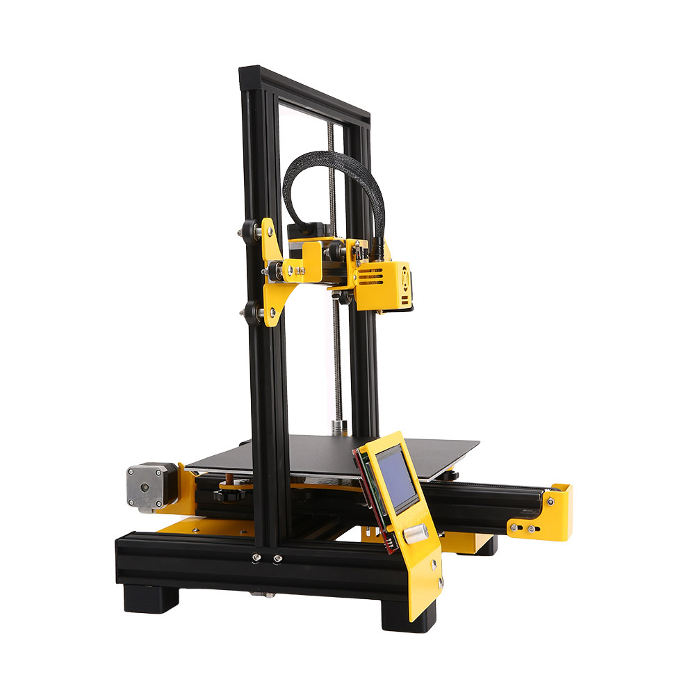
FDM 3D Printer – Most common technology for beginners and hobbyists
| Technology | Core Principle | Material Type | Precision | Best For |
|---|---|---|---|---|
| FDM | Melts thermoplastic filament; extrudes layer-by-layer | PLA, ABS, PETG, TPU | 0.1–0.3mm layer height | Hobbies, prototypes, low-strength parts |
| SLA | UV light cures liquid photopolymer layer-by-layer | Standard resin, flexible resin, high-temp resin | 0.025–0.1mm layer height | High-detail parts (jewelry, dental models) |
| SLS | Laser sinters polymer powder (no supports needed) | Nylon 12, Nylon 11, TPU powder | 0.05–0.2mm layer height | High-strength industrial parts (gears, brackets) |
| MJF | Inkjet deposits fusing agent on powder; heated roller sinters | Nylon 12, PA12 GF (glass-filled) | 0.08–0.15mm layer height | Mass-produced high-performance parts |
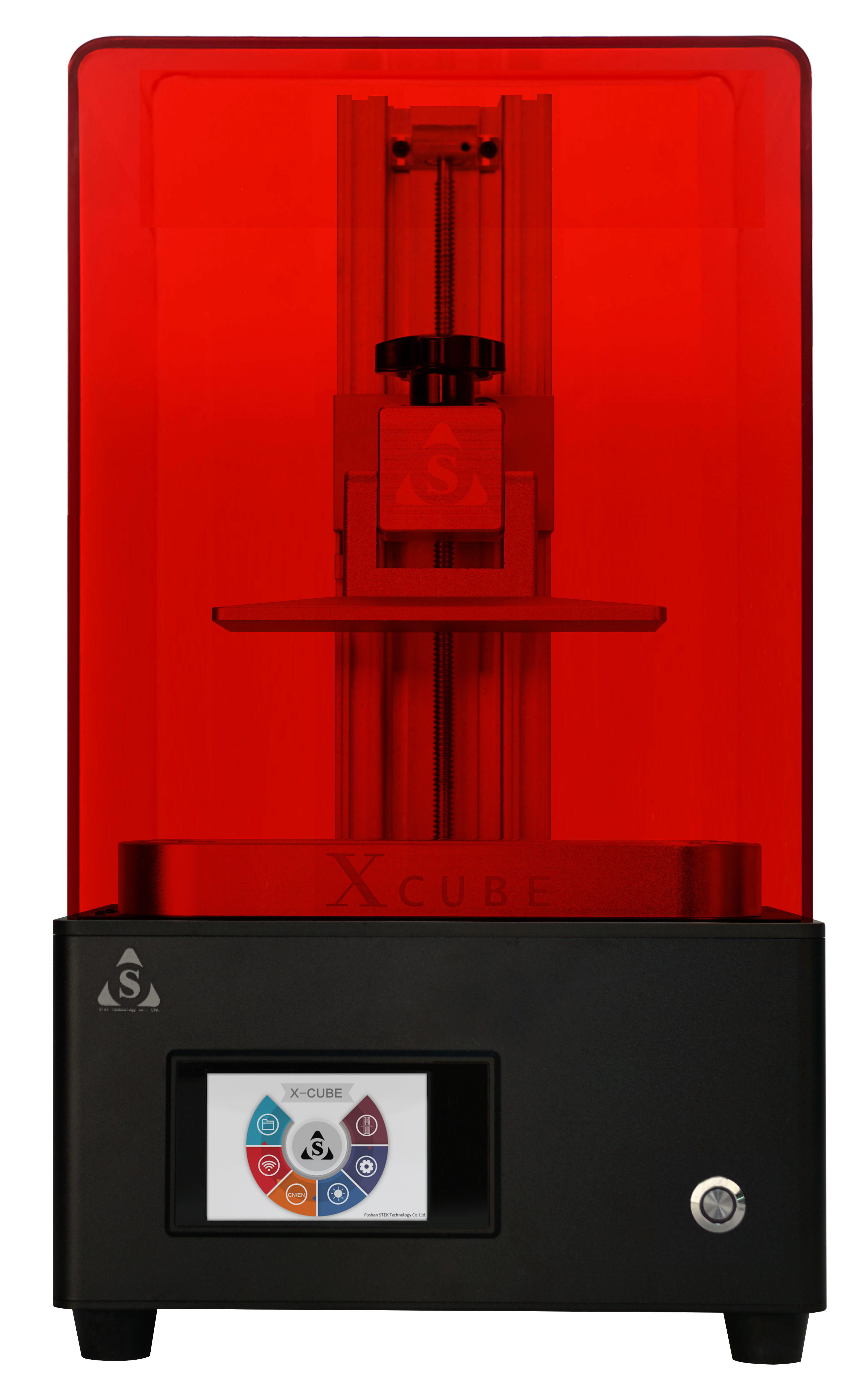
SLA 3D Printer – High precision for detailed parts
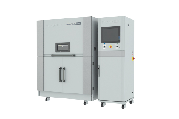
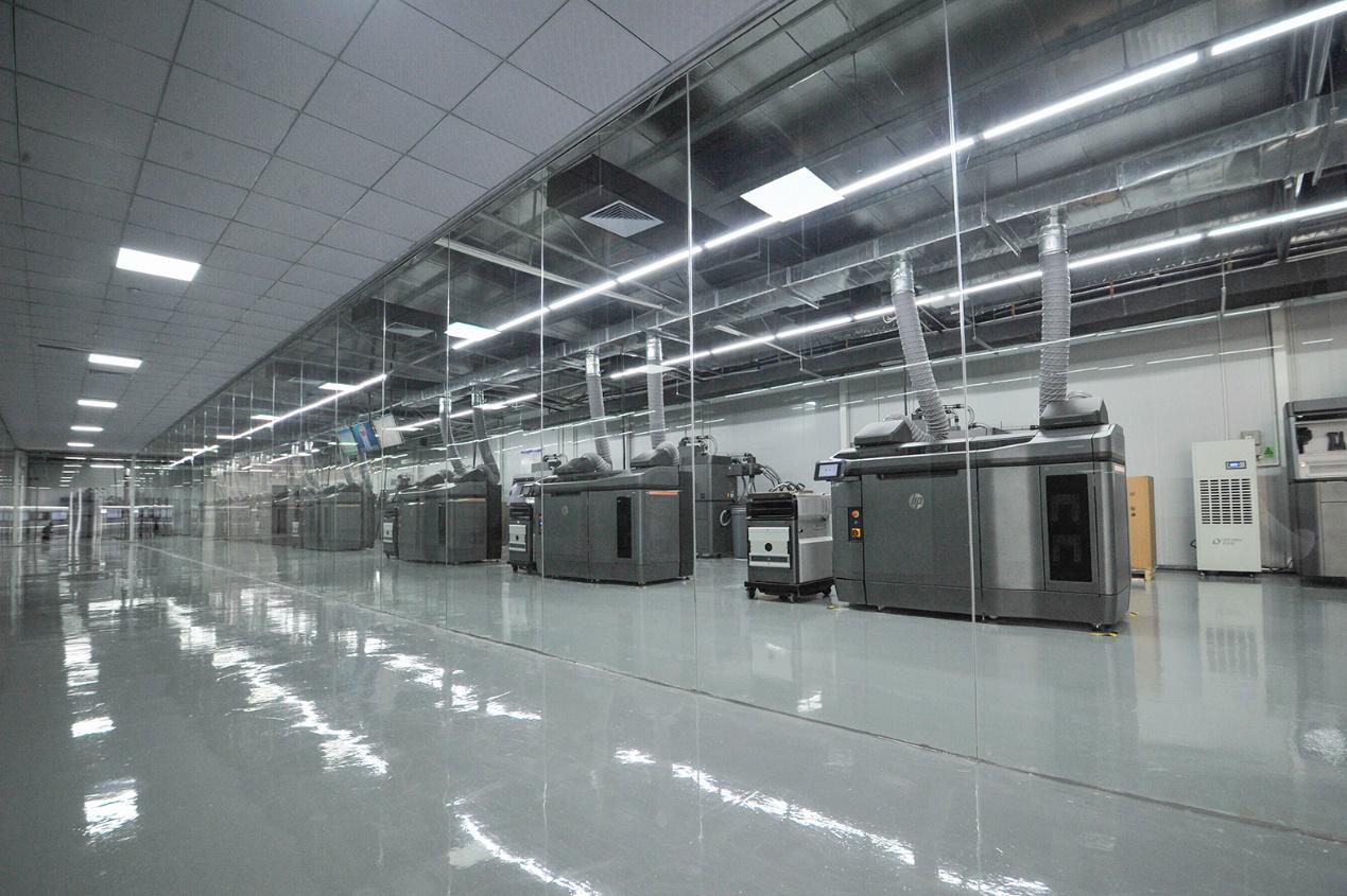
SLS 3D Printer – Industrial grade for strong parts
3. Materials Selection: Matching Material to Application
Choosing the right material is critical for achieving desired part performance. Each material offers unique properties that make it suitable for specific applications.
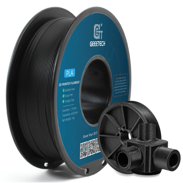
3D Printing Filament – Various types of thermoplastic materials for FDM printing
3.1 Thermoplastics (FDM Materials)
PLA (Polylactic Acid)
A biodegradable material made from renewable resources like corn starch. Easy to print with low warping and minimal odor. Ideal for prototypes, educational models, and decorative items. Limited heat resistance (softens above 60°C).
ABS (Acrylonitrile Butadiene Styrene)
Engineering-grade plastic with good impact resistance and heat resistance (up to 100°C). Requires heated bed and enclosed printing environment to prevent warping. Suitable for functional parts, toys, and automotive components.
PETG (Polyethylene Terephthalate Glycol)
Balances the ease of printing of PLA with the durability of ABS. Offers good chemical resistance, transparency, and layer adhesion. No heated bed required but benefits from one. Ideal for food-safe containers, mechanical parts, and clear components.
TPU (Thermoplastic Polyurethane)
Flexible material with rubber-like properties. Available in various shore hardness levels (from soft and flexible to rigid). Ideal for gaskets, seals, phone cases, and prosthetic components.
3.2 Resins (SLA Materials)
Standard Resin
General-purpose resin with good detail resolution and surface finish. Suitable for prototypes, jewelry, and decorative models. Offers balanced mechanical properties for most common applications.
Flexible Resin
Elastomeric resin with varying degrees of flexibility. Ideal for hinges, gaskets, and parts that require bending or stretching. Available in different hardness levels to match specific application needs.
High-Temperature Resin
Formulated to withstand higher temperatures (up to 230°C). Suitable for molds, jigs, fixtures, and parts that need to resist heat during operation or post-processing.
Biocompatible Resin
Medical-grade resin that meets biocompatibility standards. Used for dental models, surgical guides, and temporary medical devices. Requires proper handling and sterilization.
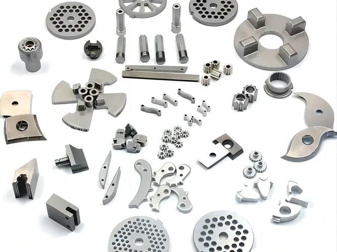
3.3 Powder Materials (SLS/MJF)
Nylon 12
Versatile engineering plastic with excellent mechanical properties. Offers high strength, toughness, and chemical resistance. Ideal for functional parts, gears, and components that require durability.
Glass-Filled Nylon
Nylon reinforced with glass fibers for increased strength and rigidity. Provides improved dimensional stability and heat resistance. Suitable for structural parts and components under load.
TPU Powder
Flexible powder material with elastomeric properties. Offers good impact resistance and flexibility. Ideal for producing complex flexible parts without support structures.
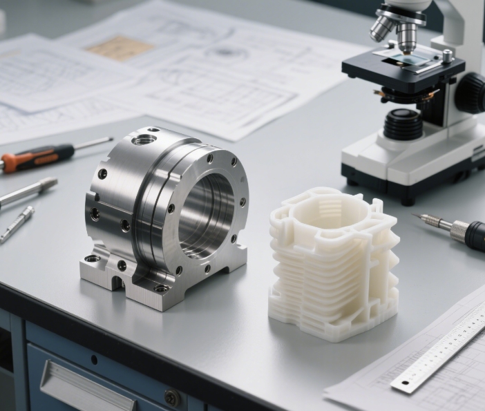
4. Surface Finishing Techniques
3D printed parts often require post-processing to improve surface finish, mechanical properties, or appearance. The choice of finishing technique depends on the printing technology and material used.
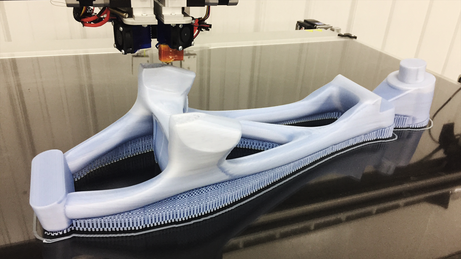
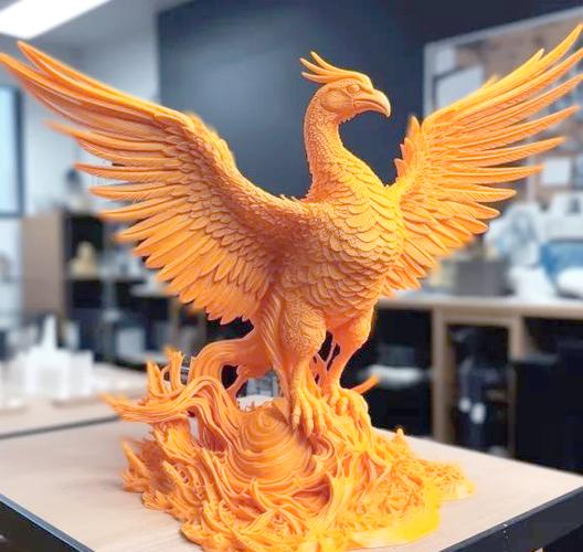
3D Printing in Progress – Layer-by-layer fabrication process
4.1 Mechanical Finishing
- Sanding: Uses sandpaper of varying grits to smooth surfaces and reduce layer lines. Start with coarse grit (200-400) and progress to finer grit (800-2000) for best results.
- Media Blasting: Propels abrasive media (glass beads, aluminum oxide) at the part surface to create a uniform matte finish. Effective for removing layer lines and improving surface texture.
- Tumbling: Uses a rotating drum with abrasive media to finish multiple parts simultaneously. Ideal for small parts and batch processing.
- Polishing: Uses polishing compounds and buffing wheels to create a glossy surface. Can be done manually or with automated equipment.
4.2 Chemical Finishing
- Vapor Smoothing: Exposes parts to solvent vapors (acetone for ABS) to dissolve the surface layer and create a smooth, glossy finish. Requires controlled environment and safety precautions.
- Dipping: Dips parts in chemical solutions to smooth surfaces. Effective for ABS and some other thermoplastics. Requires careful monitoring to avoid over-smoothing.
- Chemical Etching: Uses acids or other chemicals to remove material and improve surface finish. Common for metal 3D printed parts.
4.3 Coating and Painting
- Priming: Applies a base coat to improve paint adhesion and fill surface imperfections. Recommended before painting most 3D printed parts.
- Spray Painting: Uses aerosol paints to add color and protection. Can create various finishes from matte to glossy.
- Powder Coating: Applies dry powder electrostatically and cures it with heat. Provides durable, uniform finish for metal and plastic parts.
- Hydrographics: Transfers patterns onto part surfaces using water transfer printing. Ideal for creating complex designs and textures.
5. Industrial Applications and Use Cases
3D printing technology has transformed manufacturing across various industries, offering unique advantages for prototyping, production, and customization.
5.1 Aerospace Industry
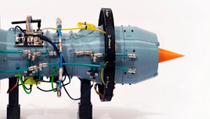
Aerospace 3D Printing – Turbine engine component produced using additive manufacturing
Aerospace companies use 3D printing to produce lightweight components with complex geometries that would be impossible with traditional manufacturing methods. Key applications include:
- Engine components (turbine blades, fuel nozzles)
- Structural parts (brackets, hinges, fasteners)
- Interior components (seat parts, air vents, control panels)
- Prototyping for new aircraft designs
Benefits include weight reduction (up to 55% compared to traditional parts), improved fuel efficiency, and reduced production time for complex components.
5.2 Medical and Dental Industry
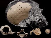
Medical 3D Printing – Patient-specific anatomical models and implants for surgical planning
3D printing has revolutionized personalized medicine by enabling the production of custom medical devices and implants. Key applications include:
- Custom prosthetics and orthotics
- Dental crowns, bridges, and aligners
- Surgical guides and templates
- Patient-specific anatomical models for surgical planning
- Biocompatible implants (bone, cranial, facial)
These applications improve patient outcomes by providing better fit, reduced surgery time, and personalized treatment solutions.
5.3 Automotive Industry
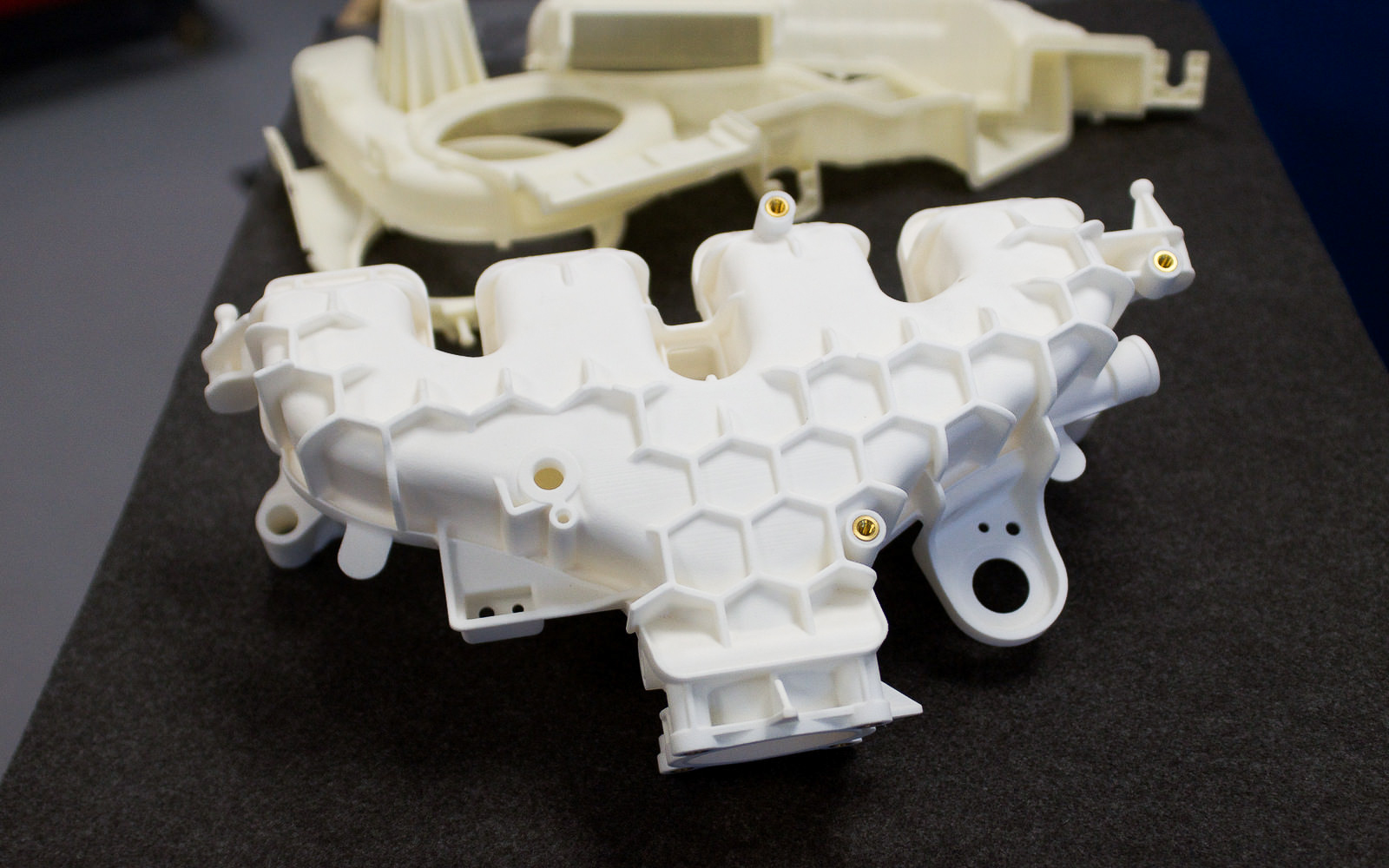
Automotive 3D Printing – Complex engine components and prototypes produced using additive manufacturing
Automotive manufacturers use 3D printing for rapid prototyping, tooling, and production of custom components. Key applications include:
- Prototyping of new vehicle designs
- Custom tooling, jigs, and fixtures
- Functional parts (air intake manifolds, brackets, sensors)
- Custom interior components and trim
- Heritage parts for classic car restoration
3D printing reduces development time by allowing engineers to quickly iterate designs and produce functional prototypes for testing.
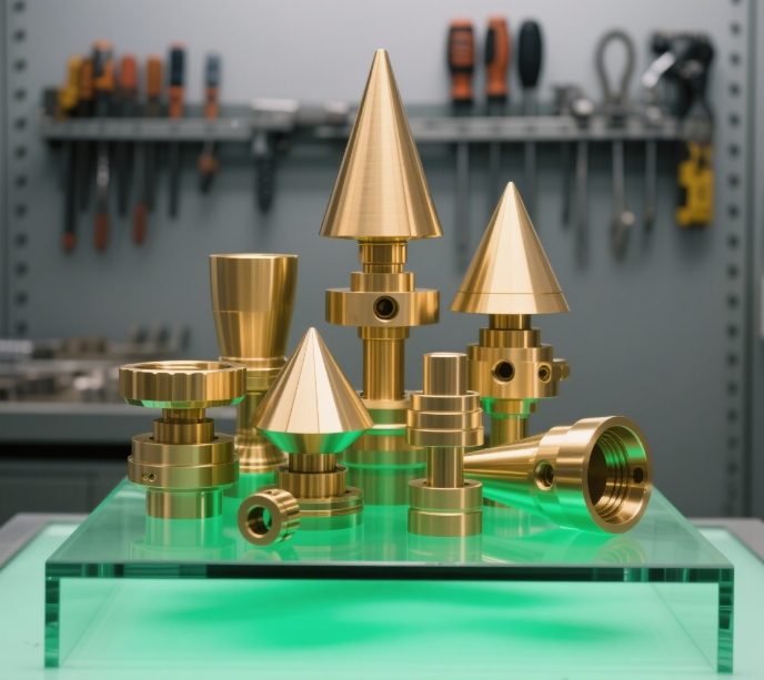
5.4 Consumer Products
Consumer product companies use 3D printing for rapid prototyping and small-batch production of custom items. Key applications include:
- Custom jewelry and fashion accessories
- Designer home goods and decor
- Custom phone cases and electronics accessories
- Toys and collectibles
- Custom packaging prototypes
3D printing enables mass customization, allowing consumers to personalize products according to their preferences.
6. Customization Process and Advantages
6.1 Customization Workflow
-
Design Consultation
Collaborate with designers to define requirements, functional needs, and aesthetic preferences.
-
3D Modeling
Create or modify 3D models using CAD software based on customer specifications.
-
Prototype Production
Print initial prototypes for customer review and feedback.
-
Design Refinement
Adjust designs based on customer feedback and functional testing.
-
Final Production
Produce the final part using the selected 3D printing technology and material.
-
Post-Processing
Apply finishing techniques to achieve desired surface quality and functionality.
-
Quality Inspection
Verify dimensions, quality, and functionality before delivery.
6.2 Advantages of Custom 3D Printing
- Design Freedom: Create complex geometries that are impossible with traditional manufacturing methods.
- Personalization: Produce unique parts tailored to specific customer needs and preferences.
- Rapid Iteration: Quickly modify and refine designs based on feedback without expensive tooling changes.
- Reduced Lead Times: Produce parts on-demand without minimum order quantities.
- Cost Efficiency: Lower costs for small production runs compared to traditional manufacturing.
- Material Variety: Choose from a wide range of materials with different properties to match application requirements.
- Reduced Waste: Additive manufacturing produces less material waste compared to subtractive methods.
7. How to Choose the Right 3D Printing Solution
Selecting the right 3D printing technology and materials requires careful consideration of several factors. Use this decision framework to guide your choice:
7.1 Define Your Requirements
- Part Function: Will the part be decorative, functional, or load-bearing?
- Accuracy Needs: What level of precision is required for your application?
- Production Volume: Are you producing a single prototype or multiple parts?
- Material Properties: What mechanical, thermal, or chemical properties are needed?
- Budget Constraints: What is your budget for equipment, materials, and post-processing?
7.2 Technology Selection Guide
For Beginners and Hobbyists
Start with FDM technology for its ease of use, low cost, and wide material selection. PLA is the best material for beginners due to its ease of printing and low warping.
For High-Detail Parts
Choose SLA technology for parts requiring high detail resolution and smooth surface finish. Ideal for jewelry, dental models, and intricate prototypes.
For Functional Industrial Parts
Select SLS or MJF technology for high-strength, durable parts that require complex geometries without support structures. Nylon materials offer excellent mechanical properties.
For Large Parts
Choose large-format FDM printers for producing large parts or prototypes. Look for printers with heated beds and enclosed chambers for better print quality with engineering materials.
7.3 Common Challenges and Solutions
- Warping: Use heated beds, enclosed chambers, or adhesive sprays to improve bed adhesion. Choose materials with lower warping tendencies like PLA or PETG.
- Layer Adhesion Issues: Increase nozzle temperature, decrease print speed, or use materials with better layer adhesion like PETG.
- Stringing: Adjust retraction settings, reduce nozzle temperature, or use higher-quality filament.
- Support Removal Damage: Use tree supports instead of normal supports, or choose support-free technologies like SLS.
- Surface Quality Issues: Use smaller layer heights, apply post-processing techniques like sanding or vapor smoothing, or choose technologies with better surface finish like SLA.
8. Cost-Benefit Analysis
3D printing offers significant cost benefits compared to traditional manufacturing methods, especially for small production runs and custom parts.
8.1 Cost Factors
- Equipment Investment: Costs vary widely depending on technology and capabilities.
- Material Costs: Different materials have different costs per unit volume.
- Post-Processing Costs: Finishing techniques add to the overall cost but improve part quality.
- Time and Labor: 3D printing reduces labor costs compared to traditional manufacturing but requires skilled operators.
8.2 Benefits and ROI
- Reduced Lead Times: Produce parts in hours instead of days or weeks.
- Lower Tooling Costs: No expensive molds or tooling required for production.
- Design Freedom: Create complex geometries that are impossible with traditional methods.
- On-Demand Production: Produce parts as needed without maintaining large inventories.
- Mass Customization: Offer personalized products without increasing production costs.
- Reduced Waste: Additive manufacturing produces less material waste compared to subtractive methods.
Expert Tips for Successful 3D Printing
- Always validate your 3D model before printing to avoid costly failures.
- Invest in quality materials for better print results and part performance.
- Calibrate your printer regularly for optimal performance.
- Use appropriate support structures for overhangs and complex geometries.
- Consider post-processing techniques to improve part quality and functionality.
- Start with simple designs and gradually move to more complex projects.
- Join online communities to learn from other 3D printing enthusiasts.
- Keep your printer clean and well-maintained for consistent results.
3D printing is a versatile technology that continues to transform manufacturing across industries. By understanding the different technologies, materials, and processes available, you can choose the right solution for your specific needs and unlock the full potential of additive manufacturing.