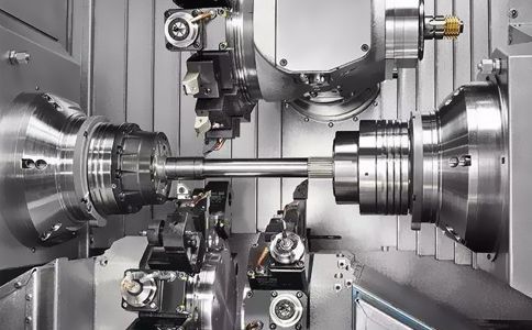
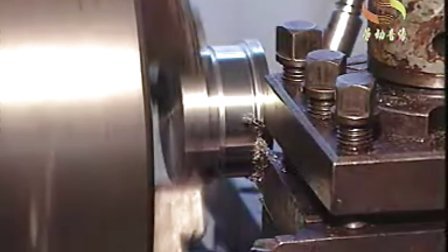
Eccentric Turning CNC Machining Services for Shafts, Sleeves & Offset Components
We provide CNC eccentric turning services for shafts, sleeves, cams, and offset rotating components. We deliver precision-engineered parts that meet your exact specifications, from prototype to full production.
- ✓ Single-offset and multi-offset turning
- ✓ Tight eccentricity and runout control
- ✓ Steel, stainless steel, aluminum, brass & more
- ✓ Prototype to production quantities
What Is Eccentric Turning?
Eccentric turning (also called offset turning) is a precision lathe process used to machine features whose rotational axis does not coincide with the main centerline of the workpiece. This specialized process allows us to create off-center bores, journals, and outer diameters that are critical for many mechanical applications.
It is commonly used for manufacturing crankshafts, camshafts, eccentric sleeves, and other drive components that convert rotational motion into reciprocating motion, or require offset bearing surfaces. Source: cnclathing.com
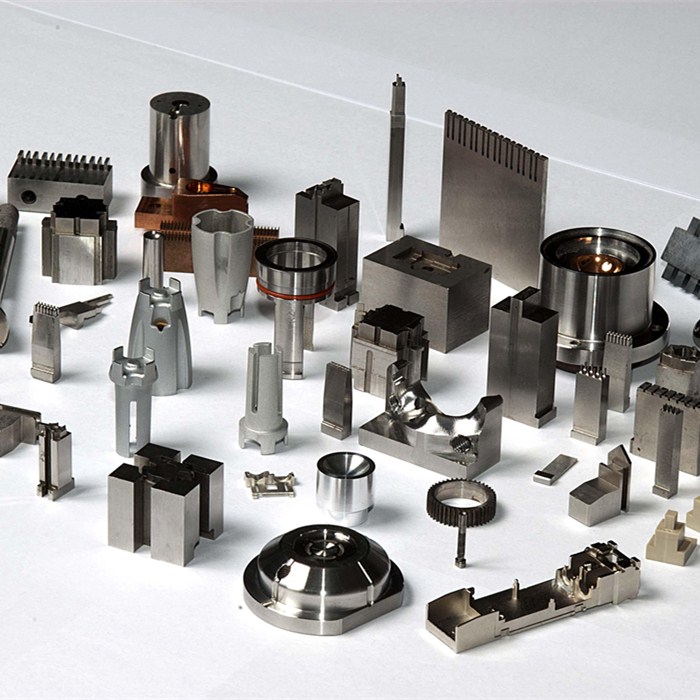
Custom Eccentric Components We Machine
- ▸ Eccentric Shafts
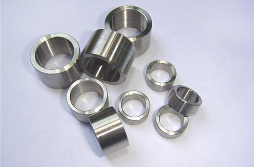
- ▸ Eccentric Sleeves & Bushings
- ▸ Offset Rollers & Journals
- ▸ Cam Drive Parts
- ▸ Crankshaft Journals & Pins
- ▸ Multi-Offset Custom Parts
Materials We Commonly Machine
| Material | Typical Use Case |
|---|---|
| Carbon Steel | General machinery components, cost-effective parts |
| Alloy Steel | Strength-critical parts, high-load drive components |
| Stainless Steel | Corrosion-resistant parts, food & medical equipment |
| Aluminum | Lightweight rotating parts, aerospace components |
| Brass / Bronze | Bushings, sleeves, low-friction wear parts |
Eccentric Turning Capabilities
| Capability | Details |
|---|---|
| Offset Types | Single eccentric, multi-offset geometries |
| Diameter Range | Custom per your drawing specifications |
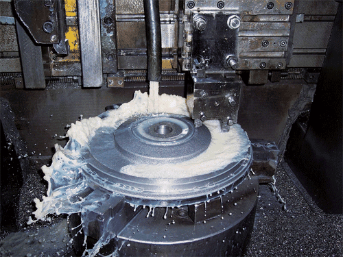
| Processes | CNC turning, milling, grinding, heat treatment |
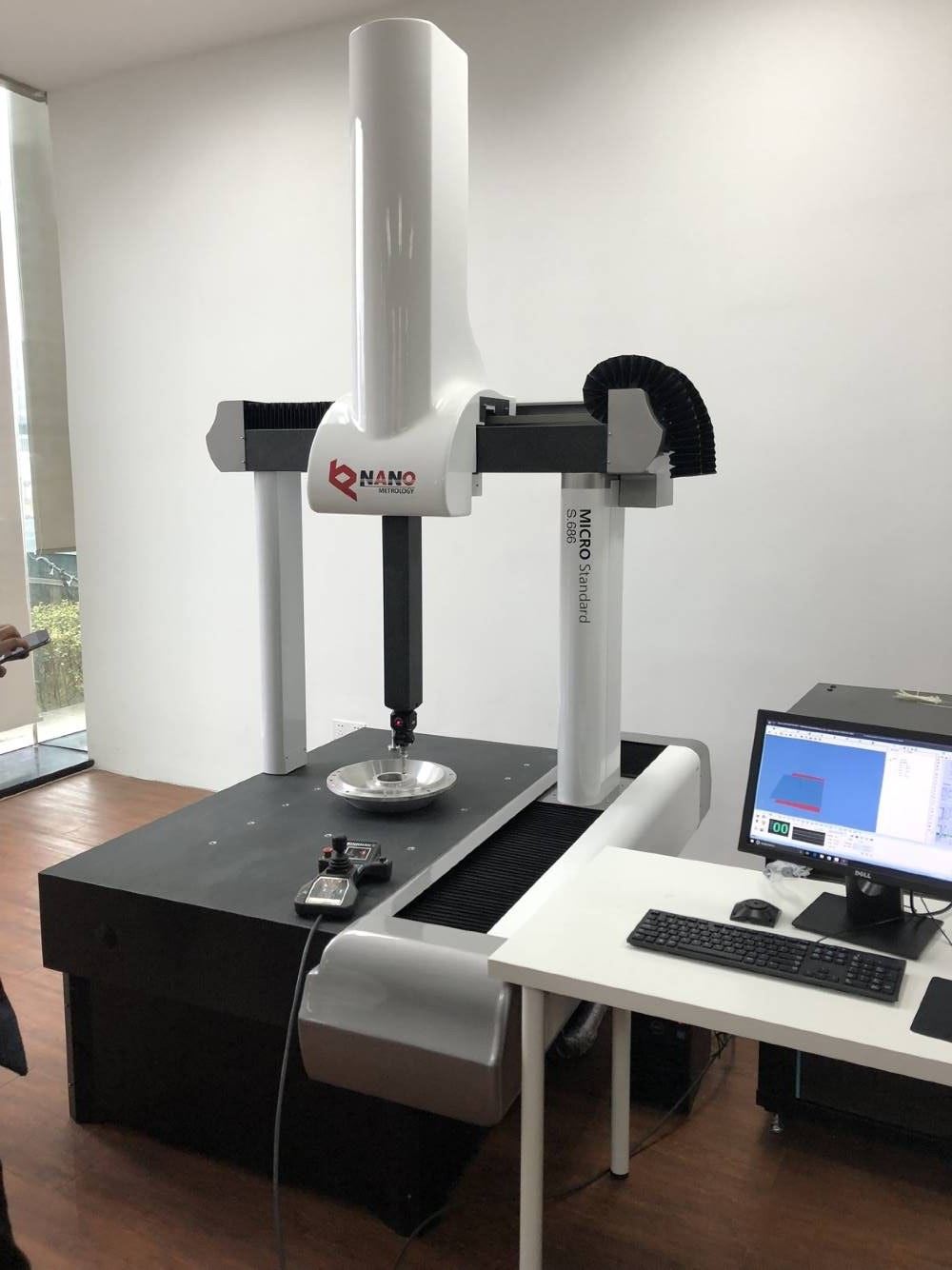
| Inspection | Dial indicator, CMM, runout testing |
| Production Volume | Prototype, low-volume, medium & high batch production |
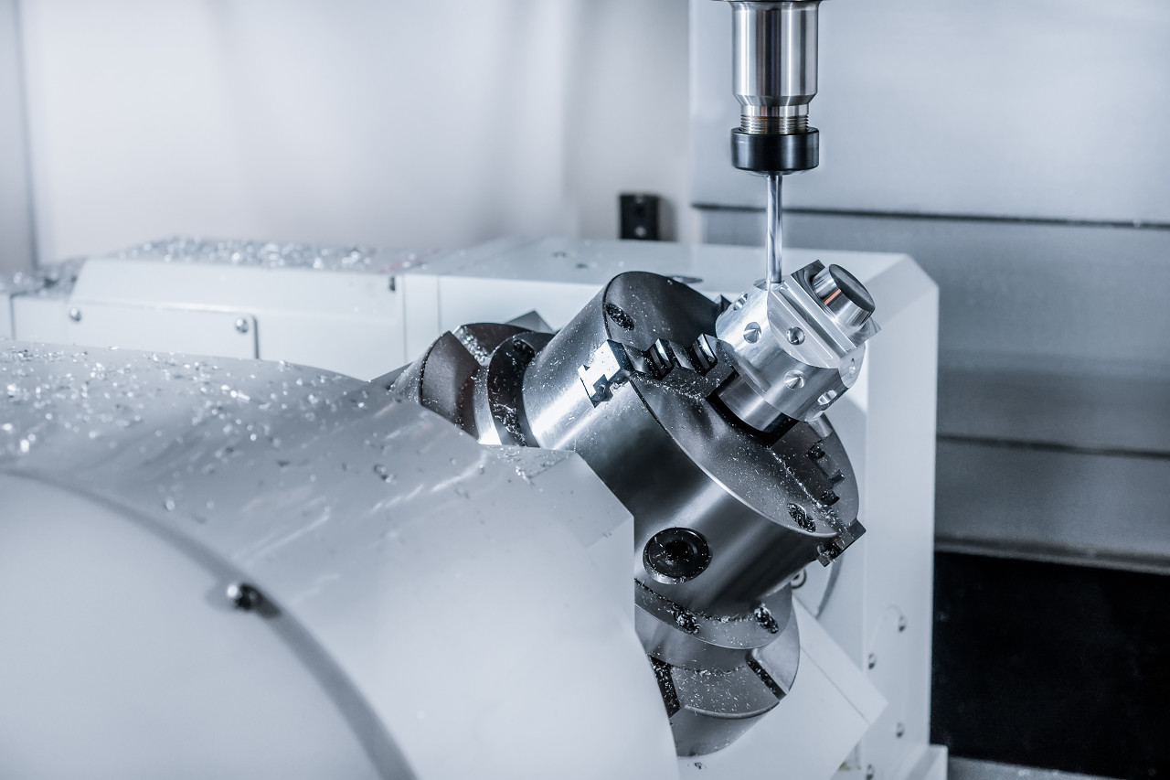
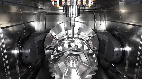
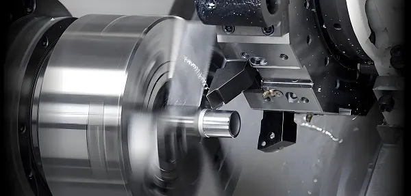
How We Control Eccentric Accuracy
Eccentric turning presents unique challenges due to the off-center load distribution, which can cause vibration and runout if not properly controlled. We implement a multi-step process to ensure your parts meet the tightest tolerance requirements:
- ✓ Precision Chucking & Custom Fixtures: We use custom-engineered fixtures to secure off-center workpieces, ensuring repeatability in batch production.
- ✓ Programmed Offset Coordinates: Our CNC systems are programmed with precise offset coordinates to maintain exact eccentricity values throughout the cutting process.
- ✓ In-Process Runout Checks: We perform intermediate inspections to verify runout and eccentricity during production, catching issues early.
- ✓ Controlled Cutting Parameters: We adjust RPM and feed rates to reduce vibration, ensuring smooth cutting even for unbalanced workpieces. Source: cmz.com
- ✓ Final CMM Inspection: All critical dimensions, including eccentricity and runout, are verified with coordinate measuring machines (CMM) before shipment.
Eccentric Turning vs Milling: Which Is Right For You?
Understanding the difference between these processes helps you choose the right manufacturing method for your part. For most offset rotating components, eccentric turning is the optimal choice.
| Feature | Eccentric Turning | Milling |
|---|---|---|
| Round bearing surfaces | Excellent | Moderate |
| Shaft-based offset parts | Best Choice | Limited |
| Complex prismatic shapes | Limited | Strong |
| Surface finish on journals | Strong | Moderate |
| Production speed for shafts | Fast & Cost-Effective | Slower |
Industries We Serve
Industrial Machinery
Drive components, eccentric actuators
Automotive
Small crank components, engine parts
Pumps & Valves
Eccentric sleeves, valve actuators
Agricultural Equipment
Farm machinery replacement parts
Packaging Machinery
Offset cam drive components
Legacy Equipment Repair
Reverse engineered replacement parts
Frequently Asked Questions
Can you machine eccentric shafts from drawings?
Yes, we fully support custom CNC production based on your 2D/3D drawings. We can work with all major CAD formats including STEP, IGES, DWG, and PDF.
What tolerance can you hold on eccentricity?
Tolerance capabilities depend on part size, material, and complexity. We can typically hold tight tolerances down to +/-0.001mm for critical applications, and we will confirm exact capabilities during your quote review.
Can you make replacement parts from samples?
Yes, we offer full reverse engineering support. We can measure your existing sample part, create the CAD model, and produce exact replacement parts, even for legacy equipment with no available drawings.
Do you accept prototype or low-volume orders?
Absolutely. We support orders from single-piece prototypes up to high-volume batch production. There is no minimum order quantity (MOQ) for our eccentric turning services.
Can you provide inspection reports with my order?
Yes, we can provide full dimensional inspection reports, material test reports (MTR), and PPAP documentation upon request, to meet your quality and compliance requirements.
Request a Quote for Eccentric CNC Machining
Upload your drawing, and we’ll get back to you with a detailed quote within 24 business hours.