The core challenges in CNC machining of 304 stainless steel lie in its high cutting force, severe work hardening, high cutting temperature, and pronounced tool wear. Austenitic 304 stainless steel exhibits a specific cutting force of 2450 MPa—25% higher than 45# steel—with work hardening creating a 0.1-0.3mm surface layer reaching 1500 MPa hardness. Cutting zone temperatures typically exceed those of Common steel by 200-300°C. Below is a systematic solution framework:
Tool Selection: Prioritizing Wear Resistance and Anti-adhesion
Tool Materials should prioritize YG-series carbides (e.g., YG8) or TiAlN coatings for superior wear and adhesion resistance. High-speed steel (HSS) cutoff tools work for diameters under φ40mm, while larger workpieces require carbide tools. Optimal Tool Geometry parameters:
- Rake angle 10°-15°, clearance angle 5°-8° to maintain cutting edge sharpness and minimize work hardening
- Zero axial rake angle to prevent chip clogging in grooves during cutoff operations
- Nose radius ≤0.8mm to reduce minor flank wear; 0.2mm negative land on cutting edge enhances impact resistance
Cutting Parameters: Balancing Efficiency and Tool Life
Implement a “medium speed, moderate feed, layered cutting” strategy with these parameters:
| Operation Type | Tool Material | Cutting Speed (m/min) | Feed Rate (mm/r) | Depth of Cut (mm) |
|---|---|---|---|---|
| Rough Milling | YG8 Carbide | 40-60 | 0.1-0.2 | 1-3 |
| Finish Milling | TiAlN Coated | 60-100 | 0.05-0.1 | 0.1-0.5 |
| High-Speed Milling | TiAlN Coated | 450-500 | 0.10-0.15 | 0.7-0.8 (axial) |
Note: High-speed milling parameters require rigid machine tools and enhanced cooling. Depth of cut should not exceed 60-70% of tool diameter to prevent chatter.
Process Optimization: Minimizing Hardening and Thermal Distortion
- Machining Sequence: Remove 70-80% stock in roughing (leaving 0.5-1mm), perform 24-hour stress relief annealing, then semi-finish/final machining. Use climb milling for roughing to reduce friction against work-hardened surfaces.
- Chip Control: Implement periodic retraction for chip breaking during cutoff operations. Leave 1-2mm stock on solid workpieces for manual chip breaking to prevent tool dwelling in hardened layers.
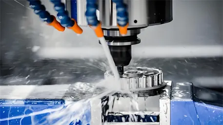
- Coolant System: Utilize emulsion or sulfurized oil with S/Cl extreme pressure additives at ≥20L/min flow rate to maintain continuous cutting zone cooling.
Troubleshooting Common Issues
- Tool Chipping: Limit tool overhang to ≤3× diameter, reduce feed rate by 20%, and switch to “fish belly” style tool holders for enhanced rigidity.
- Poor Surface Finish: Hone rake faces to Ra0.4 or better; use circular ramping entry for finishing passes instead of direct plunge cutting.
- Dimensional Inaccuracy: Control thermal distortion through “rough-cool-finish” cycles; conduct final inspections at 20°C ambient temperature.
Practical Machining Tips
Seasoned machinists report 30% longer tool life with properly lapped rake faces. The “single pass + retraction” method increases efficiency by 50% compared to oscillating cuts for φ40-80mm bar stock. Ensure machine rigidity with ≥7.5kW spindle power and use shrink-fit or hydraulic tool holders to minimize runout.
These integrated strategies typically deliver 40% higher productivity and 50% lower tool consumption for 304 stainless steel machining. Success hinges on synergistic optimization of tooling, parameters, and cooling, combined with proactive control of work hardening and thermal effects. Always conduct preliminary test cuts to fine-tune parameters based on actual tool wear patterns and surface quality measurements.

