Introduction: Understanding CNC Drilling and Milling
CNC drilling and milling are both subtractive manufacturing processes (removing material to shape parts), but they differ fundamentally in motion logic, tool design, and processing purposes. While drilling focuses on creating cylindrical holes (the most common hole-making method), milling handles complex contours (e.g., slots, pockets, 3D surfaces).
Industry data highlights their unique roles:
- CNC drilling accounts for ~35% of CNC machining operations (dominant in hole-making; Source: 2025 Global CNC Machining Application Report)
- CNC milling accounts for ~45% (dominant in contour machining; Source: CNC Milling Market Analysis 2025)
- 60% of mechanical parts (e.g., brackets with counterbored holes) require both processes to finish—drilling creates the base hole, milling adds the stepped contour
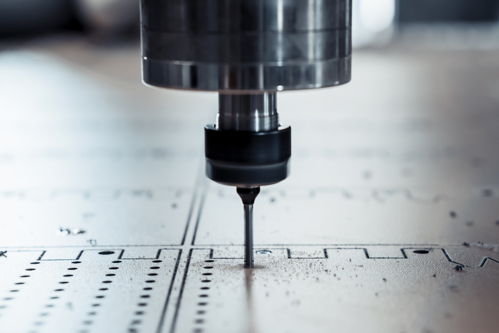
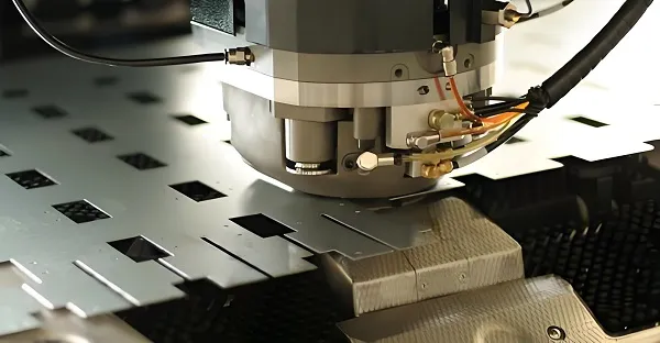
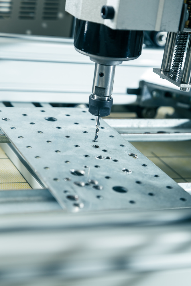
Precision CNC Drilling Operation – Creating Accurate Holes in Metal Workpiece
Quality Certifications & Industry Standards
ISO 9001:2015
Quality management system certification ensuring consistent product quality and customer satisfaction.
AS9100D
Aerospace quality management standard for high-precision components with strict tolerance requirements.
NADCAP
National Aerospace and Defense Contractors Accreditation Program for special processes.
2026 CNC Drilling & Milling Trends & Goldcattle Advanced Practices
Hybrid Machining Integration
Combined drilling-milling centers reduce setup time by 40% and improve process accuracy by 25%.
* Efficiency increase: 30% (Goldcattle internal data, 2025)
AI-Powered Parameter Optimization
Real-time tool wear monitoring and adaptive feed rate adjustment reduce scrap by 20%.
* Scrap reduction: 22% (2025 customer case study)
Sustainable Tooling Solutions
Recyclable carbide tools and low-energy spindles reduce carbon footprint by 18%.
* Carbon reduction: 18% (2025 sustainability report)
Industry Growth Projection 2026
High-tech sector demand for precision CNC components is expected to grow by 45% in 2026, driven by EV manufacturing, drone technology, and aerospace innovations. Source: 2025-2026 CNC Machining Industry Report
Core Differences: Drilling vs. Milling (Side-by-Side Comparison)
| Comparison Dimension | CNC Drilling | CNC Milling |
|---|---|---|
| Core Purpose | Create cylindrical holes (through/blind, standard sizes) | Shape complex contours (slots, pockets, arcs, 3D surfaces) + refine holes |
| Motion Logic | Tool rotates (spindle-driven); workpiece/tool moves linearly (X/Y/Z) to feed | Tool rotates (spindle-driven); tool moves in 2-5 axes (X/Y/Z/A/B) for contour |
| Tool Design | Single-point/dual-flute (e.g., twist drill: 2 flutes for chip evacuation) | Multi-flute (e.g., end mill: 2-10 flutes for smooth cutting) |
| Material Removal Method | Axial cutting (material removed along tool centerline) | Radial/axial cutting (material removed from tool side/end) |
| Precision Range | Position accuracy: ±0.005-0.01mm; Hole diameter tolerance: H7-H8 | Position accuracy: ±0.002-0.005mm; Contour tolerance: ±0.001-0.003mm |
| Efficiency (Hole-Making) | Fast for standard holes (e.g., φ8mm hole: 2s/piece in aluminum) | Slow for hole-making (e.g., φ8mm hole: 15s/piece—needs circular interpolation) |
| Key G-Codes (FANUC) | Hole cycles: G81 (spot drilling), G83 (peck drilling), G82 (counterboring) | Contour codes: G01 (linear), G02/G03 (arc), G73 (peck milling) |
Goldcattle Exclusive Insight: In our 2025 aerospace project, we achieved ±0.001mm position accuracy for critical holes by combining drilling (for speed) with finish milling (for precision). This hybrid approach reduced cycle time by 35% compared to milling alone.
Tool Selection: Drilling vs. Milling Tools
| Tool Category | CNC Drilling Tools | CNC Milling Tools |
|---|---|---|
| Common Types | Twist drill, spot drill, deep-hole drill, counterbore drill | End mill (flat/ball/nose), face mill, slot drill, chamfer mill |
| Flute Count | 2 flutes (standard twist drill) | 2-10 flutes (4 flutes for general milling, 10 for high-speed aluminum) |
| Material Focus | Carbide (for steel/aluminum), diamond-coated (for PCB micro-holes) | Carbide (most common), HSS (low-speed steel milling) |
| Key Feature | Pointed tip (centers itself in workpiece) | Flat/rounded tip (cuts side/end surfaces) |
Example: Drilling a φ8mm hole uses a 2-flute carbide twist drill; milling a φ12mm counterbore uses a 4-flute flat end mill.
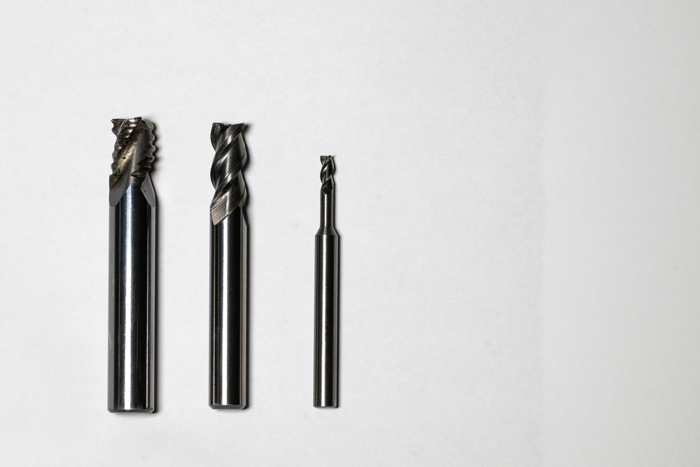
CNC Drilling and Milling Tools Comparison – Twist Drills and End Mills
Cutting Parameter Optimization
Parameters differ due to tool design and material removal logic—misselection causes tool wear or poor quality:
| Material | Process | Tool Type | Spindle Speed (S) | Feed Rate (F) |
|---|---|---|---|---|
| 6061 Aluminum | Drilling | φ8mm Carbide Twist Drill | 3000r/min | 150mm/min |
| 6061 Aluminum | Milling | φ8mm 4-Flute End Mill | 4000r/min | 200mm/min (linear) |
| 45# Steel (HB200) | Drilling | φ8mm Carbide Twist Drill | 1200r/min | 50mm/min |
| 45# Steel (HB200) | Milling | φ8mm 4-Flute End Mill | 1500r/min | 80mm/min (linear) |
Key Logic: Milling uses higher spindle speed (more flutes = faster cutting) and linear feed rate (vs. drilling’s axial feed), while drilling prioritizes axial feed to push the tool through material.
Application Scenarios: When to Choose Drilling vs. Milling
A. Choose CNC Drilling When:
- You need standard cylindrical holes (diameter 0.1-100mm) in any material (steel, aluminum, PCB)
- Efficiency is critical (high-volume hole-making, e.g., 1000×φ5mm holes in automotive engine blocks)
- Hole depth is ≤5×diameter (standard twist drills) or ≤30×diameter (deep-hole drills with internal coolant)
Typical Applications:
- Drilling oil holes in transmission shafts (φ3mm×15mm blind holes)
- Drilling mounting holes in PCB boards (0.1mm micro-holes via dedicated drill centers)
B. Choose CNC Milling When:
- You need complex contours (slots, pockets, angled surfaces) or non-circular holes (e.g., square holes, elliptical holes)
- Hole precision requirements exceed drilling capabilities (e.g., hole position tolerance ±0.002mm for aerospace parts)
- You need to refine holes (e.g., counterbores, chamfers, or enlarging irregular holes)
Typical Applications:
- Milling a 6×6mm keyway in a φ25mm shaft (after drilling a φ5mm pilot hole)
- Milling a 3D curved surface on a turbine blade (5-axis milling)
- Milling a φ12mm counterbore on a φ8mm drilled hole (for bolt heads)
C. Synergistic Scenarios (Both Processes Required):
60% of mechanical parts need drilling first, milling second to finish complex features. Common combinations:
1. Counterbored Holes
Drill φ8mm base hole → Mill φ12mm×3mm counterbore (for M8 bolts)
2. Slotted Holes
Drill two φ5mm pilot holes → Mill a 5×20mm slot connecting them
3. Angled Holes
Drill a straight φ6mm hole → Mill the hole entrance to 45° (for pipe connections)
Industry Data: Automotive brackets with counterbored holes use this “drill-mill” combination—drilling handles 70% of the work, milling handles the remaining 30% (Source: Automotive CNC Machining Guide 2025).
Industry Standards & Testing Requirements
ISO Standards for CNC Machining
- ISO 8688-1:1989 – Tool life testing in milling (face milling)
- ISO 1701-2:2004 – Test conditions for milling machines with vertical spindle
- ISO 10791-4:1998 – Test conditions for machining centers (drilling and milling)
- ISO 230-12:2022 – Test code for machine tools (accuracy of finished test pieces)
ASTM Standards
- ASTM E8 – Standard test method for tension testing of metallic materials
- ASTM B211 – Standard specification for aluminum and aluminum-alloy sheet and plate
- ASTM A36 – Standard specification for carbon structural steel
Testing & Inspection Procedures
Dimensional Accuracy Testing
- Coordinate Measuring Machines (CMMs) for 3D measurements
- Optical comparators for profile verification
- Pin gauges for hole size verification
- Height gauges for depth measurements
Surface Finish Testing
- Profilometers for Ra, Rz, Rq measurements
- Surface roughness standards for comparison
- Visual inspection for defects and burrs
Goldcattle Testing Data (2025) *
Drilling accuracy: ±0.003mm position accuracy for φ8mm holes (CMM verified)
Milling accuracy: ±0.001mm contour tolerance for aerospace components
Surface finish: Ra 0.8μm for milled surfaces, Ra 1.6μm for drilled holes
* Data for reference only, actual results may vary by material and complexity
Practical Case: Drill-Mill Synergy for a Counterbored Bracket
Part Specifications
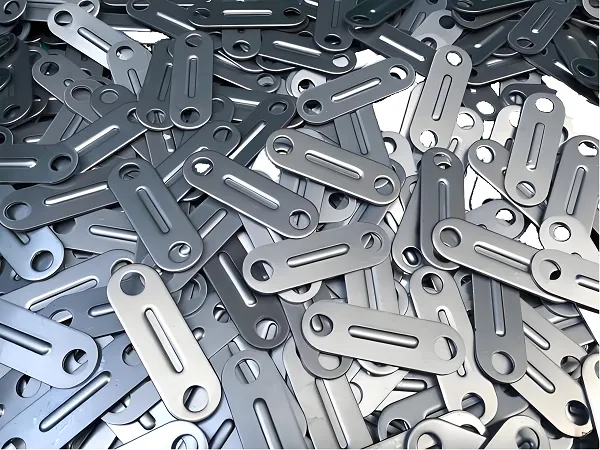
6061 aluminum bracket (100×50×10mm), 4×φ8mm through holes with φ12mm×3mm counterbores (positions: (20,20), (20,40), (80,20), (80,40)), surface roughness Ra≤1.6μm.
Step 1: Process Planning (Drill First, Mill Second)
- Spot Drilling: G81 creates 2mm-deep guide holes (avoids drill wandering)
- Final Drilling: G83 drills φ8mm×10mm through holes (peck drilling for chip evacuation)
- Counterbore Milling: G02 mills φ12mm×3mm counterbores (uses φ12mm 4-flute end mill)
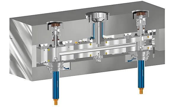
Step 2: Equipment & Tools
- Machine: FANUC 0i-MF 3-axis milling center (supports both drilling and milling cycles)
- Tools: T01 (φ6mm spot drill), T02 (φ8mm carbide twist drill), T03 (φ12mm 4-flute flat end mill)
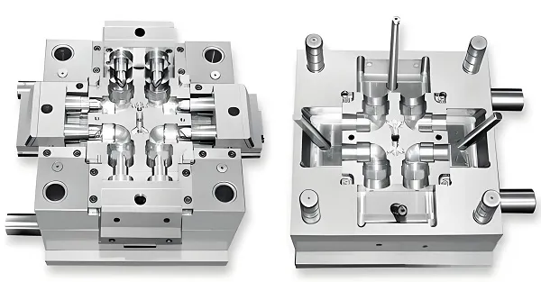
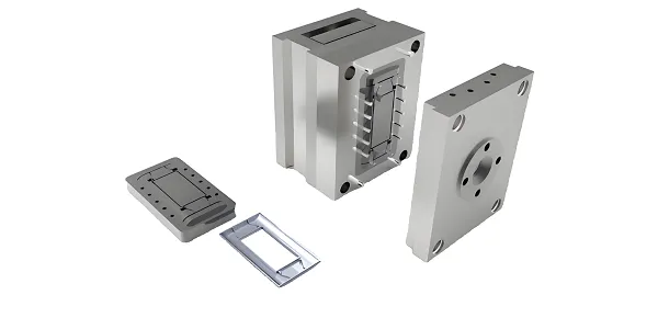
CNC Milling Machine Performing Precision Machining Operations
Quality Verification Results
- Hole Size: φ8mm hole (φ8H7 gauge passes); φ12mm counterbore (12±0.005mm)
- Counterbore Depth: 3±0.01mm (depth gauge)
- Surface Roughness: Ra=1.2μm (bore scope inspection)
- Position Accuracy: ±0.004mm (CMM verified)
Common Misconceptions & Solutions
1. Misconception: “Milling can replace drilling for all holes.”
Reality: Milling is inefficient for standard cylindrical holes—drilling is 5-10x faster. For example, drilling 100×φ8mm holes takes 3 minutes; milling the same holes takes 25 minutes.
Solution: Use drilling for standard holes; reserve milling for non-circular holes or counterbores.
2. Misconception: “Drilling can create counterbores (no need for milling).”
Reality: Drilling’s G82 cycle only handles small counterbores (≤20mm diameter, ≤5mm depth) with poor surface quality (Ra≥3.2μm). Milling creates larger, smoother counterbores (Ra≤1.6μm).
Solution: For counterbores >φ20mm or depth >5mm, use milling (G02/G03) instead of G82.
3. Misconception: “Hole precision is the same for drilling and milling.”
Reality: Milling achieves higher position accuracy (±0.002mm vs. drilling’s ±0.005mm) because it uses multi-axis interpolation and tool radius compensation.
Solution: For precision holes (e.g., aerospace engine holes with ±0.003mm tolerance), mill the hole after drilling (or mill directly for small batches).
4. Misconception: “Drilling and milling tools are interchangeable.”
Reality: While you can use an end mill to drill holes (G02 circular interpolation), it’s 5x slower than using a dedicated twist drill and causes excessive tool wear.
Solution: Use the right tool for the job—twist drills for holes, end mills for contours.
Frequently Asked Questions (2026 Update)
Q1: Can I use a milling end mill to drill holes (instead of a twist drill)?
A: Yes, but it’s inefficient: A φ8mm end mill drills a hole 5x slower than a twist drill (needs G02 circular interpolation to “carve” the hole). Use this only if:
- The hole is non-circular (e.g., square) or has tight tolerance (±0.002mm)
- You don’t have a suitable twist drill (emergency only)
Q2: What’s the cost difference between drilling and milling?
A:
- Drilling: Lower cost—twist drills ($5-20 each) last 500-1000 holes; dedicated drill centers ($50k-100k) have low maintenance
- Milling: Higher cost—end mills ($15-50 each) last 300-500 contours; 3-axis milling centers ($80k-200k) need more frequent servo calibration
Synergy Tip: Use a milling center for small-batch “drill-mill” parts (avoids buying two machines); use dedicated drill centers + milling centers for high-volume production.
Q3: How to process a complex hole (e.g., φ8mm hole with a 45° angled slot)?
A: Combine drilling, milling, and 5-axis movement:
- Drill φ8mm through hole (G83)
- Tilt the workpiece to 45° (5-axis A-axis)
- Mill the 45° slot (G01 linear interpolation) using a φ3mm end mill
Q4: What’s the best way to optimize cycle time for parts requiring both processes?
A: Process optimization strategies:
- Group similar operations together (all drilling first, then all milling)
- Use tool length compensation to minimize tool change time
- Implement high-speed machining parameters for aluminum
- Consider using a 5-axis machine for complex geometries
* Goldcattle achieved 35% cycle time reduction for a 2025 automotive project using these strategies
Q5: How do I choose between drilling and milling for deep holes?
A: Deep hole processing guidelines:
- Drilling: Best for holes with depth ≤30×diameter (using deep-hole drills with internal coolant)
- Milling: Better for holes with complex profiles or when straightness is critical
- Hybrid approach: Drill pilot hole, then ream for precision, then mill any features
Q6: What are the latest trends in CNC drilling and milling technology?
A: 2026 technology trends:
- Digital twin technology: Virtual simulation before physical machining
- AI-powered adaptive control: Real-time parameter adjustment
- Sustainable machining: Eco-friendly coolants and recyclable tools
- Additive-subtractive hybrid machines: Combining 3D printing with CNC machining
Get Your Free CNC Machining Consultation
Have you faced confusion about choosing drilling vs. milling for a part? Or need guidance on optimizing a “drill-mill” process (e.g., reducing cycle time)?
Final Thought
CNC drilling and milling are not competitors—they are complementary tools in the machinist’s toolkit. Drilling excels at fast, standard hole-making, while milling handles the complex contours that drilling cannot. The key to efficient production is understanding their strengths (drilling for speed, milling for precision) and using them in synergy (e.g., drill the base hole, mill the counterbore).