Table of Contents
- Basic Understanding of CNC Part Design
- 3 Key Preparations Before Design
- Detailed Operation Record: 5 Steps to Connect Design & Machining
- 6 Essential Machining Tips for Beginners
- Common Issues & Solutions
- Conclusion: The Key to Moving From “Knowing How” to “Doing Well”
1. Basic Understanding of CNC Part Design
First, it’s critical to understand: CNC part design is not just “drawing a shape”—it’s “designing a part that can be precisely machined”. It requires combining “design logic” with “CNC machining characteristics”—for example, what shapes the machine can cut, how far the tool can reach, and how the material might deform. All these factors must be considered in advance during the design phase.
For beginners, there’s no need to pursue complex structures right away. Start with “simple parts + standard processes”: design an aluminum bracket with holes or a steel bushing with steps, for instance. Master the basic logic first, then gradually move to more advanced designs.
2. 3 Key Preparations Before Design
Skipping preparation before design often leads to problems during machining (e.g., a hole too small for the tool to fit, or a material too soft to avoid deformation). These 3 preparation steps are non-negotiable:
(1) Interpret Design Requirements: Clarify “What Needs to Be Done”
- Start with 3 questions: What is the part used for? (e.g., “securing components” or “transmitting power”) What loads will it bear? (e.g., “light load” or “heavy load”) What are the installation requirements? (e.g., “must align with other parts, tolerance ±0.05mm”)
- Translate requirements into design parameters: For example, a “bracket for securing” → choose aluminum alloy (light and easy to machine), 5mm thickness (sufficient for support), and 8mm hole diameter (to match M8 screws).
(2) Choose the Right Material: Match “Design Needs + Machining Difficulty”
Beginners should prioritize materials that are “easy to machine and low-cost,” avoiding difficult-to-machine materials (such as stainless steel or titanium alloy) initially. A comparison of common materials is provided below:
| Material Type | Characteristics | Machining Difficulty | Suitable Scenarios |
|---|---|---|---|
| Aluminum Alloy (e.g., 6061) | Lightweight, soft, smooth cutting | Low | Brackets, housings, light-load parts |
| Low-Carbon Steel (e.g., Q235) | Moderate hardness, sufficient strength | Medium | Shafts, fixing bases, heavy-load parts |
| Acrylic | Transparent, easy to cut | Low (note: prevent chipping) | Decorative parts, simple housings |
(3) Confirm Machine Parameters: Avoid “Unmachinable Designs”
CNC machines are not “all-purpose.” Confirm the machine’s core parameters before design (ask machinists or check the equipment manual):
- Machine Travel: For example, if the X-axis has a maximum travel of 300mm, the part length cannot exceed 300mm (otherwise, it won’t fit).
- Spindle Speed Range: For example, if the maximum speed is 8000rpm, set the speed to 5000-6000rpm when machining aluminum alloy (to stay within the safe range).
- Tool Specifications: For example, if the smallest end mill the machine can hold is 2mm, the width of narrow slots in the design cannot be less than 2mm (otherwise, the tool won’t fit).
3. Detailed Operation Record: 5 Steps to Connect Design & Machining
This section outlines the “practical workflow,” with specific operations and notes for each step—beginners can follow it directly:
Step 1: 3D Modeling (Use Beginner-Friendly Software, e.g., SolidWorks, UG)
- Software Selection: Beginners should prioritize SolidWorks (easy to operate, with abundant tutorials) or the free FreeCAD (ideal for those on a budget).
- Core Modeling Steps:
- Create a “reference plane”: Use the “Front Reference Plane” as the base, for example (to ensure a unified reference for all subsequent features).
- Draw a “sketch”: For example, draw the bracket’s outline (a rectangle, 50mm long × 30mm wide). Remember to “constrain the sketch” (e.g., align edges with coordinate axes to prevent deformation later).
- Add “features”: For example, “extrude” the sketch (to 5mm thickness), then draw a hole (8mm diameter, extrude through the part).
- Note for Beginners: Feature order matters! Extrude the main body first, then drill holes. If you drill holes first and then extrude, the hole position will shift if you later adjust the main body’s dimensions.
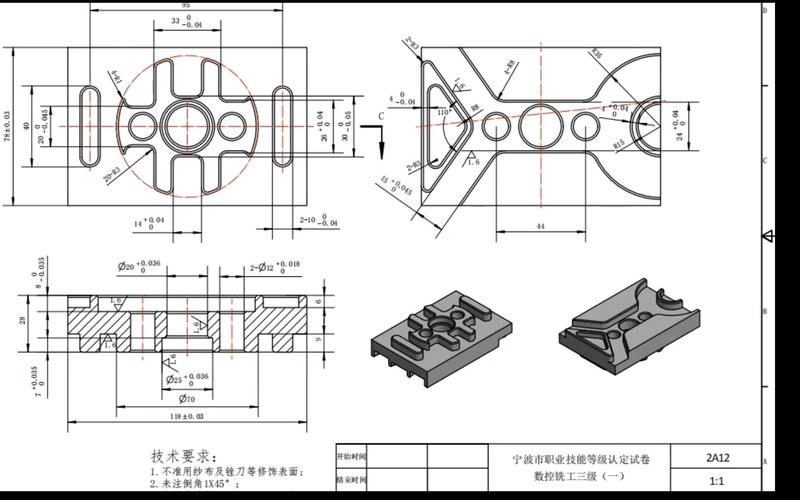
Step 2: Export 2D Engineering Drawings (The “Instruction Manual” for Machining)
3D models are for computers, while 2D engineering drawings are for machinists and machines. They must clearly indicate the “machining basis”:
- Annotation Content:
- Dimensions: For example, main body length 50±0.1mm, hole center distance 20±0.05mm. Set tolerances based on requirements—there’s no need to specify high precision for all dimensions (to avoid increasing machining costs).
- Surface Roughness: For example, “Ra1.6” for the part surface (smooth to the touch) and “Ra6.3” for non-mating surfaces (no need for fine finishing).
- Machining Requirements: For example, “chamfer holes to C1” (to avoid sharp edges) and “unnoted fillets R0.5”.
- Note: Use either “First Angle Projection” or “Third Angle Projection” for engineering drawings (follow factory conventions; First Angle is commonly used in China, while Third Angle is prevalent in 欧美 markets). Do not mix the two.
Step 3: CNC Programming (Convert Design into “Machine Movements”)
Programming tells the machine “which tool to use, which path to follow, and how deep to cut.” Beginners can use Mastercam (beginner-friendly) or UG CAM:
- Import the 3D Model: Ensure the model has no “broken faces.” If there are, repair them in the modeling software (otherwise, programming errors will occur).
- Select Tools: For example, use a “10mm end mill” for contour milling and an “8mm drill bit” for drilling 8mm holes.
- Set Cutting Parameters:
- Aluminum Alloy: Spindle speed 5000-6000rpm, feed rate 1000-1500mm/min (faster for soft materials).
- Low-Carbon Steel: Spindle speed 2000-3000rpm, feed rate 500-800mm/min (slower for hard materials to avoid tool wear).
- Generate Toolpaths: For example, “mill the contour first → drill holes → chamfer finally.” Toolpaths should be “continuous” (to avoid frequent tool lifts and save time).
- Simulation & Verification: This step is non-negotiable! Use software to simulate the toolpath and check for “tool collisions” (tools hitting fixtures or workpieces) or missed cuts. Export the “NC Program” (instruction file for the machine) only after simulation confirms no issues.
Step 4: Pre-Machining Checks (Avoid “Errors as Soon as the Machine Starts”)
After transferring the NC program to the machine, perform these 3 checks before machining:
- Tool Installation: Confirm the tool model is correct (e.g., don’t install an 8mm end mill if a 10mm one is required). Ensure the tool is “clamped tightly” (looseness will cause dimensional inaccuracies).
- Workpiece Clamping: Secure the workpiece to the machine table with a fixture (e.g., use a vice to clamp an aluminum plate). Ensure the workpiece is “level” (use a dial indicator to align it, with an error of no more than 0.02mm).
- Tool Setting: Tell the machine “where the tool is”—use a “tool setter” or “edge finder.” For example, set the Z-axis (determine the distance from the tool to the workpiece surface). After tool setting, “perform a test cut” (e.g., mill a small slot and measure its dimensions).
Step 5: Test Cutting & Mass Production
- Test Cutting: Machine 1 part first, and focus on checking 3 points: whether dimensions meet tolerances (measure with calipers or micrometers), whether the surface is smooth (no burrs or tool marks), and whether hole positions are correct (compare with a coordinate measuring machine or template).
- Mass Production: Start mass production only after the test cut is successful. Conduct “regular sampling inspections” during production (e.g., measure 1 part every 10 machined parts) to avoid dimensional deviations caused by tool wear.
4. 6 Essential Machining Tips for Beginners
These tips are “pitfall-avoidance guides” summarized by experienced machinists—they are more important than simply learning operations:
(1) “Leaving Machining Allowance” Is Safer Than “Cutting to Size in One Pass”
Beginners often try to “machine to the final size in one pass,” but machine vibration and tool wear easily lead to deviations. The correct approach is:
- Leave a “0.1-0.2mm allowance” during rough machining (e.g., rough-cut to 5.2mm if the final thickness is 5mm).
- Finish-cut to the final size (5mm) during finishing—this ensures higher dimensional accuracy.
(2) High Speed for Soft Materials; Low Speed for Hard Materials
Different materials have different “cutting characteristics.” Remember this simple rule:
- Soft Materials (Aluminum Alloy, Acrylic): High spindle speed (5000-8000rpm) and fast feed rate (1000-2000mm/min) for faster machining and smoother surfaces.
- Hard Materials (Steel, Stainless Steel): Low spindle speed (2000-4000rpm) and slow feed rate (500-1000mm/min) to avoid tool burning (overheating and wear).
(3) Don’t Use “Large Tools” for Narrow Slots; Drill Deep Holes “In Multiple Passes”
- Narrow Slots (e.g., 3mm width): Use a 3mm end mill (avoid 4mm tools, which can’t fit). If no exact-sized tool is available, use a smaller tool to “cut back and forth” (e.g., use a 2mm tool to cut a 3mm slot in 2 passes).
- Deep Holes (e.g., 20mm deep, 8mm diameter): Don’t drill all the way through in one pass. Drill in 3-4 passes (drill 5-6mm each time, then lift the tool to clear chips) to avoid drill breakage caused by chip clogging.
(4) Clamp Workpieces “Firmly” and Avoid Pressing “Weak Areas”
- Use Sufficient Clamping Force: For example, clamp the workpiece with a vice—ensure it’s tight (looseness causes workpiece movement during machining), but not too tight (e.g., excessive force will deform acrylic).
- Avoid Weak Areas: For example, when machining a “slender shaft” (5mm diameter, 100mm length), don’t clamp the middle. Clamp one end and support the other with a “center” (to prevent shaft bending during machining).
(5) Minimize “Tool Lifts and Idle Moves” in Toolpaths to Save Machining Time
- Minimize Tool Lifts: For example, when milling multiple holes, design toolpaths to “move directly from one hole to the next” (no need to lift the tool high), reducing non-cutting time.
- Minimize Idle Moves: Group “machining at the same depth” during programming (e.g., mill all 5mm-deep slots first, then 10mm-deep slots) to avoid frequent depth adjustments.
(6) Keep a “Machining Log” to Avoid Repeating Mistakes
Spend 5 minutes recording a log after each machining session:
- Record Content: Material, tool model, cutting parameters, problems encountered (e.g., “Aluminum alloy machined at 6000rpm had tool marks—adjust to 5500rpm next time”), and solutions.
- Purpose: Reference the log directly when machining similar parts later, eliminating the need for repeated trial and error.
5. Common Issues & Solutions
Beginners will likely encounter these issues during machining. Don’t panic—use the solutions below:
| Common Issue | Possible Causes | Solutions |
|---|---|---|
| Dimensional Deviation (e.g., 50.2mm instead of the required 50mm) | 1. Incorrect tool setting; 2. Tool wear; 3. Loose workpiece | 1. Re-set the tool and calibrate with a tool setter; 2. Replace with a new tool; 3. Re-clamp the workpiece and check clamping force |
| Burrs or Tool Marks on the Surface | 1. Incorrect cutting parameters (too low speed, too fast feed); 2. Dull tool edge | 1. Increase speed (e.g., adjust aluminum alloy machining from 4000rpm to 5500rpm) and reduce feed rate; 2. Sharpen or replace the tool |
| Tool Collision (Tool Hits Fixture/Workpiece) | 1. No toolpath simulation; 2. Incorrect Z-axis coordinate setting during tool setting | 1. Always simulate the toolpath to confirm no collisions; 2. Re-set the tool and verify the Z-axis coordinate (e.g., set “workpiece surface as Z0”) |
| Drilled Holes Misaligned (Incorrect Center Distance) | 1. Wrong hole coordinates in programming; 2. Unaligned workpiece | 1. Check hole coordinates in the 3D model and re-program; 2. Align the workpiece with a dial indicator to ensure it’s parallel to the machine’s coordinate axes |
6. Conclusion: The Key to Moving From “Knowing How” to “Doing Well”
For beginners, the core of CNC part design is not “mastering software skills”—it’s “building a connected mindset between ‘design’ and ‘machining’.” When designing, always ask yourself: “Can this structure be machined?” and “Will machinists understand this annotation?”
Start by “replicating simple parts”: Find an existing CNC part (e.g., a small bracket), practice drawing its 3D model, creating 2D engineering drawings, and writing simple programs. Then verify through actual machining. After practicing 3-5 simple parts, try designing slightly more complex structures (e.g., sloped surfaces or multi-step shafts).
Remember: Mistakes are normal—what matters is learning from them (e.g., if a tool collision occurs, always simulate the toolpath next time). With gradual accumulation, you’ll move from a “beginner” to a “practitioner capable of independently completing CNC part design and machining.”
I can help you further optimize this English version—for example, adjusting technical terms to better align with North American or European CNC industry conventions, or adding simple diagrams (e.g., toolpath simulation sketches) to enhance readability. Would you like me to create a simplified CNC machining parameter cheat sheet (tailored for beginners) to pair with this article?

