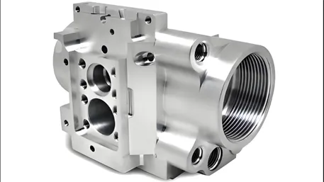
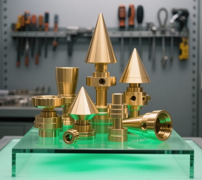
The term “milling” refers to a machining operation that involves removing material using a rotating cutting tool during the manufacturing process. It is a highly flexible machining method capable of achieving different shapes and surface treatments on a wide range of materials. Additionally, milling encompasses various types of mechanical equipment.
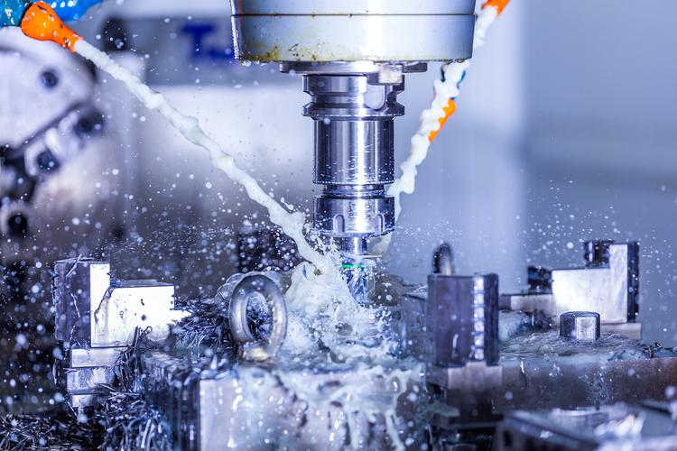
Milling is a metal cold – working method. The workpiece moves in a straight line while a high – speed rotating milling cutter cuts it to form planes, grooves, or contoured surfaces. Drilling, reaming, and other machining operations can also be carried out.
I. Types of CNC Milling Processes
CNC milling centers can machine a variety of complex features with high precision, such as threads, chamfers, slots, etc. However, different milling processes are required to achieve these features, including:
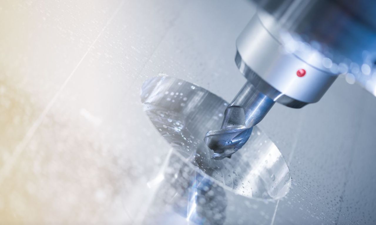
Face MillingIn face milling, the axis of rotation of the cutting tool is perpendicular to the workpiece surface. Cutting mainly relies on the cutting edges on the end face of the tool, while the teeth on the outer circle of the tool play an auxiliary role in improving the surface quality. Usually, face milling is carried out right after plain milling. It can be used to machine fine contours and leaves a high – quality finish on the workpiece surface. Face milling typically uses a face mill, which is usually equipped with multiple replaceable inserts to enhance machining efficiency and tool life.
Angular MillingThe axis of the angular – milling tool is usually perpendicular or parallel to the machined surface to meet different angular machining requirements. It is suitable for machining grooves, chamfers, slots, and other complex features. In traditional three – axis milling, a dovetail milling cutter can be used to machine inclined grooves, or a conical cutter head can be used to machine chamfers. More advanced 5 – axis CNC milling machines can freely rotate the tool in multiple directions to achieve more complex inclined – surface machining.
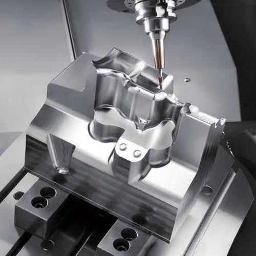
Form MillingThis process uses special – purpose tools to machine complex contours. Commonly used tools include concave and convex milling cutters, which can form surface contours, rounded corners, and circular grooves in a single cut. This method is suitable for machining parts with high – precision complex shapes.
Other Milling Processes
Profile Milling: The tool cuts along the inclined or vertical surface of the workpiece. Usually, a special profile milling cutter is used. During the machining process, the tool can be parallel or perpendicular to the workpiece surface. It is mainly used to machine the outer contour of the workpiece, complex curved surfaces, or free – form curves.
Gang Milling: It is a type of form milling. Multiple milling cutters are installed on the same spindle to simultaneously machine multiple parallel surfaces or multiple grooves. These milling cutters can have different shapes, sizes, or widths, enabling the completion of multiple machining tasks in a relatively short time and improving production efficiency. It is suitable for batch processing of complex parts.
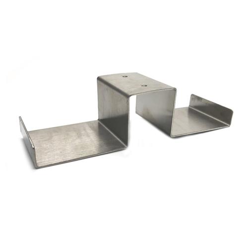
Straddle Milling: This process uses two oppositely arranged milling cutters to simultaneously mill both sides of the workpiece, ensuring consistent dimensional accuracy on both sides and achieving efficient symmetrical machining. It is suitable for batch processing of symmetrical structures such as symmetrical grooves and symmetrical steps.
Each of the above milling processes has its own characteristics. Reasonable selection of the appropriate processing method can improve production efficiency, optimize product quality, and meet the manufacturing requirements of different parts.
Plain MillingAlso known as Surface Milling, it typically uses a horizontal milling cutter, with the axis of rotation of the tool parallel to the workpiece surface. Cutting is mainly accomplished by the circumferential cutting edges of the tool. It is suitable for machining large planes or removing a large amount of material. Depending on the feed direction, it can be divided into climb milling and conventional milling.
II. CNC Milling Workflow
Design StageIn the initial stage of CNC milling, designers use computer – aided design (CAD) software to create a product model. Commonly used software includes SolidWorks and Autodesk, which assist designers in accurately drawing the shape and dimensions of the required parts.
Programming StageAfter the design is completed, the CAD file needs to be converted into G – code, the language that CNC machines can understand. Through computer – aided manufacturing (CAM) software, the design file is transformed into instructions that can be executed by the machine, enabling automated processing.
Machine SetupDuring the machine – setup stage, the workpiece needs to be fixed on the worktable, and the appropriate tool is selected. At the same time, the operator also needs to set the initial coordinates to ensure precise positioning during the machining process.
III. Advantages of CNC Milling
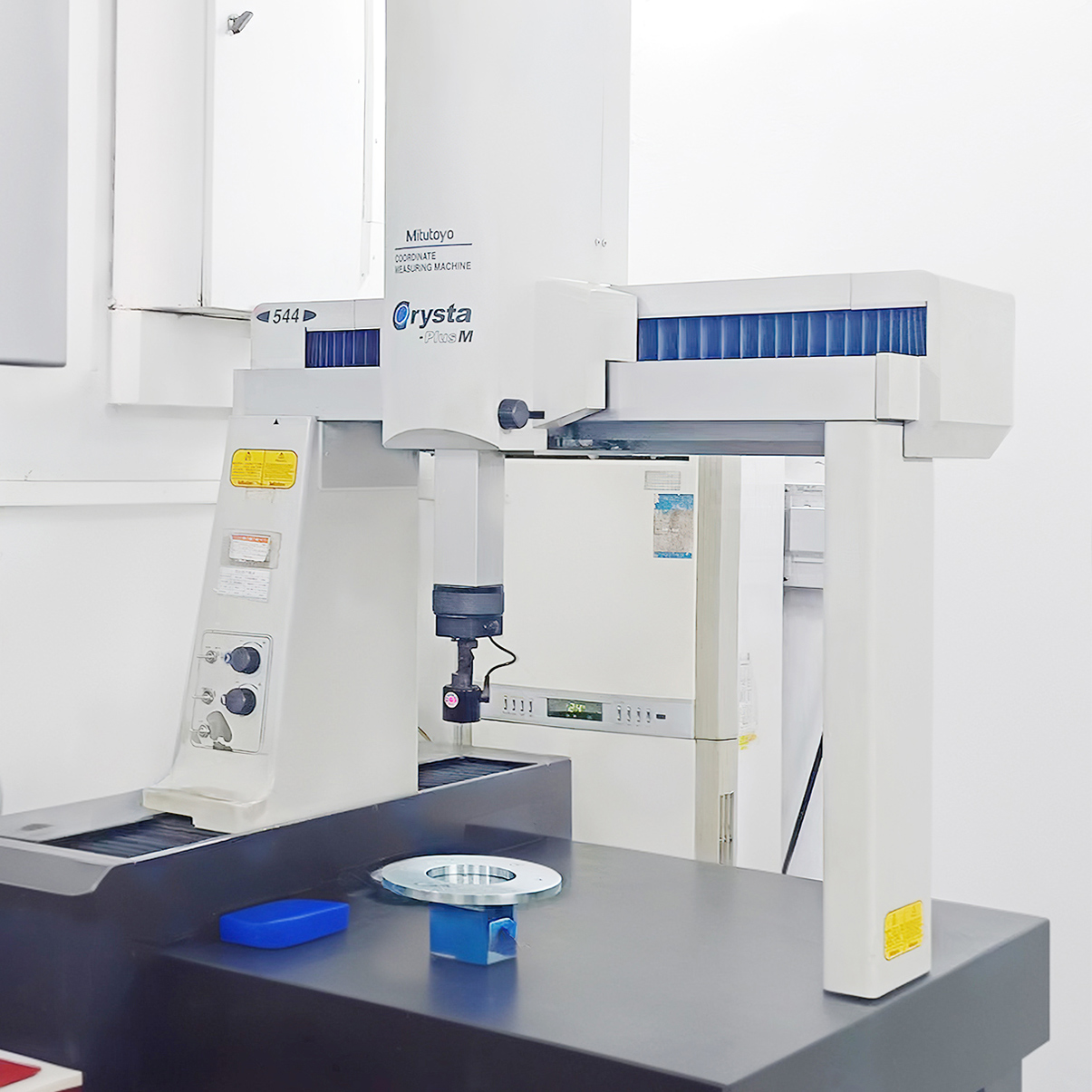
High Precision and Dimensional Stability: CNC milling can achieve machining accuracy at the micron level, ensuring the consistency of each part.
Ability to Machine Complex Shapes: Whether it is a simple plane or a complex three – dimensional structure, CNC milling can handle it with ease.
High – Efficiency Production Capacity: Due to its high degree of automation, CNC milling can significantly improve production efficiency and shorten the delivery cycle.
IV. Suitable Machining Situations for Milling
(1) Curved contours on the workpiece, such as straight lines, arcs, threads, or spiral curves, especially non – circular curves and tabulated curves given by mathematical expressions.(2) Spatial curves or surfaces with a given mathematical model.(3) Parts with simple shapes but numerous dimensions and difficult to inspect.(4) Inner cavities, the interior of boxes, etc., which are difficult to observe, control, and inspect when processed by ordinary machine tools.(5) Holes or planes with strict dimensional requirements.(6) Simple surfaces or shapes that can be machined incidentally in one clamping.(7) General machining content that can effectively improve productivity and reduce labor intensity by using CNC milling.
V. Key Points of Milling
Operators should wear tight – fitting work clothes with cuffs tightened, wear safety helmets, wear safety goggles during high – speed milling, wear masks when milling cast iron parts, and it is strictly prohibited to wear gloves during operation to prevent the hand from being caught between the rotating tool and the workpiece.
Before operation, check whether all components and safety devices of the milling machine are safe and reliable, and check whether the electrical part of the equipment is in good condition in terms of safety and reliability.
When loading and unloading the workpiece, retract the worktable to a safe position. When tightening the workpiece with a wrench, the direction of force should avoid the milling cutter to prevent the wrench from slipping and hitting the tool or fixture.
Use special pads to hold the milling cutter when installing and removing it, and do not directly hold the milling cutter by hand.
When milling irregular workpieces and using vices, dividing heads, and special fixtures to hold the workpiece, the center of gravity of the irregular workpiece and the vice, dividing head, special fixture, etc. should be placed as much as possible in the middle of the worktable to avoid uneven stress on the worktable and deformation.
During rapid or automatic feed milling, do not move the worktable to the two extremes to prevent damaging the screw rod.
When the machine is running, do not adjust, measure the workpiece, or change the lubrication method to prevent the hand from touching the tool and injuring the fingers.
Do not brake the milling cutter by hand before it completely stops rotating.
Do not remove chips by hand or blow them with the mouth during milling to prevent chips from injuring the skin and eyes.
When the machine is in rapid feed, disengage the handwheel clutch to prevent the handwheel from rotating rapidly and injuring people.
When reversing the worktable, first stop the reversing handle in the middle position and then reverse. Do not reverse directly.
When milling key – way shafts or cutting thin workpieces, be careful not to damage the dividing head or the worktable surface.
When milling a plane, a cutter head with more than four cutters must be used, and appropriate cutting parameters should be selected to prevent the machine from vibrating during milling.
After work, stop the worktable in the middle position and lower the knee to the lowest position.
For CNC vertical milling machines, before work, pre – select relevant work procedures, spindle speed, tool feed rate, tool movement trajectory, and continuous over – travel according to the process requirements. Place the electrical knob in the “adjustment” position for a test run. After confirming that there are no problems, place the electrical knob in the automatic or semi – automatic position for work.
VI. Frequently Asked Questions
What materials can be processed by CNC milling?CNC milling is suitable for a variety of materials, including metals (such as aluminum, steel), plastics, wood, etc. However, for some materials, such as ceramics or certain composite materials, the machining is more difficult and requires special treatment.
What are the limitations of CNC milling?Despite its advanced technology, CNC milling has some limitations. For example, machining of internal vertical corners or very complex small – scale structures may be restricted. In addition, high – hardness materials may cause faster tool wear, thus affecting production efficiency.
Comparison between CNC milling and other manufacturing technologiesWhen comparing CNC milling with other manufacturing technologies (such as 3D printing), each has its own advantages and disadvantages. CNC milling is usually superior to 3D printing in terms of accuracy and surface finish, while 3D printing has an edge in rapid prototyping and complex geometries. In terms of cost – effectiveness, the choice of which technology to use depends on specific project requirements and budget.