1. Straight Answer: Yes—CNC Drilling Is a Core Machining Capability
CNC machines (including CNC lathes, mills, and dedicated drill centers) are highly capable of drilling holes—even outperforming traditional manual drilling in precision, efficiency, and complex hole machining. In fact, CNC drilling accounts for ~35% of all CNC machining operations (Source: 2025 Global CNC Machining Application Report), supporting industries from automotive (engine cylinder holes) to aerospace (turbine blade cooling holes).
CNC drilling achieves this via:
- Programmed positioning: X/Y/Z axes move the drill to exact coordinates (e.g., ±0.005mm accuracy).
- Controlled spindle speed/feed: Optimizes cutting parameters for different materials (e.g., aluminum vs. steel).
- Automated cycles: Peck drilling (for deep holes) or countersinking (for screw heads) reduces human error.
2. Why CNC Drilling Outperforms Traditional Manual Drilling
CNC drilling solves key pain points of manual drilling (e.g., position deviation, inconsistent hole size) with 5 core advantages:
|
Advantage
|
CNC Drilling Performance
|
Traditional Manual Drilling Performance
|
Industry Data Support
|
|
Position Accuracy
|
±0.005-0.01mm (via servo-driven axes)
|
±0.1-0.3mm (reliable on operator skill)
|
Reduces hole position error by 95% (Source: CNC Precision Study 2025)
|
|
Dimensional Consistency
|
Batch hole size deviation ≤0.003mm
|
Batch deviation ≥0.05mm (due to hand tremors)
|
99.8% first-pass qualification rate for CNC (vs. 85% manual)
|
|
Efficiency
|
3-5x faster (200 holes/hour for φ5mm steel holes)
|
40-60 holes/hour (operator fatigue slows speed)
|
Cuts drilling time by 60% for automotive parts (Source: Manufacturing Efficiency Report)
|
|
Complex Hole Machining
|
Drills blind holes, stepped holes, angled holes
|
Limited to simple through holes (angle/ depth hard to control)
|
70% of aerospace complex holes rely on CNC (Source: Aerospace Machining Guide)
|
|
Automation
|
24/7 unattended operation (with auto-loaders)
|
Requires constant operator supervision
|
Reduces labor cost by 40% for high-volume production
|
3. Key Types of CNC Machines for Drilling
Not all CNC machines drill holes the same—selection depends on part type, hole complexity, and production volume:
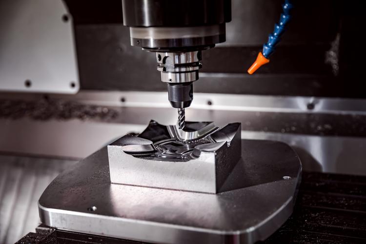
A. CNC Milling Centers (3/4/5-Axis)
- Core Strength: Drills holes in irregular parts (e.g., brackets, housings) via X/Y/Z-axis positioning; 5-axis models handle angled holes (e.g., 45° holes in engine blocks).
- Typical Application: Drilling 6×φ8mm through holes in an aluminum bracket (positioned at (10,20), (30,20), etc.).
- Key Feature: Supports “drill-tap-mill” integration (drills holes, taps threads, and mills chamfers in one setup).
B. CNC Turning Centers (With C-Axis)
- Core Strength: Drills radial/axial holes in rotational parts (e.g., shafts, bushings); C-axis indexes the workpiece to drill holes at specific angles (e.g., 90° cross holes in a shaft).
- Typical Application: Drilling a φ6mm axial hole (along Z-axis) and a φ4mm radial hole (perpendicular to Z-axis) in a φ30×100mm steel shaft.
- Key Feature: Uses “live tooling” (rotating tools on the turret) to drill while the workpiece is clamped.
C. Dedicated CNC Drill Centers (PCB/Metal)
- Core Strength: High-speed drilling for small, dense holes (e.g., PCB circuit boards, thin metal sheets); some models drill up to 10,000 holes/hour.
- Typical Application: Drilling 0.1mm micro-holes in a PCB (used in smartphones).
- Key Feature: Specialized spindles (10,000-60,000r/min) for micro-drilling.
4. Critical CNC Drilling Technologies (Precision & Safety)
To achieve high-quality holes, master these 4 core technologies:
A. Tool Selection: Match Drill to Material & Hole Type
|
Drill Type
|
Material Compatibility
|
Hole Type Application
|
Key Parameters
|
|
Twist Drill
|
Steel, aluminum, copper (general-purpose)
|
Through holes, blind holes (depth ≤5×diameter)
|
High-speed steel (HSS): Vc=20-50m/min; Carbide: Vc=80-150m/min
|
|
Spot Drill
|
All materials (pre-drilling guide)
|
Guides twist drills (prevents wandering)
|
Tip angle 90° (matches twist drill tip angle)
|
|
Deep-Hole Drill
|
Steel, stainless steel (depth >5×diameter)
|
Deep blind holes (e.g., 20×φ5mm holes)
|
Uses internal coolant holes (for chip evacuation)
|
|
Counterbore Drill
|
Steel, aluminum (for bolt heads)
|
Stepped holes (e.g., φ8mm hole + φ12mm counterbore)
|
Counterbore depth = bolt head height (e.g., 3mm for M8 bolts)
|
B. Peck Drilling: Solve Deep Hole Chip Evacuation
- Problem: Deep holes (depth >5×diameter) trap chips, causing drill breakage or hole scuffing.
- Solution: Peck drilling (G83 code for FANUC) — drills in small “pecks” (e.g., 2×diameter per peck) and retracts to evacuate chips.
- Program Example (φ5mm hole, depth 30mm):
- G83 X10 Y20 Z-30 R2 Q10 F100 // Q10=peck depth 10mm, R2=safe distance above workpiece
C. Spindle Speed & Feed Rate Optimization
- Rule of Thumb: Harder materials = lower speed + lower feed; softer materials = higher speed + higher feed.
|
Material
|
Drill Material
|
Spindle Speed (S)
|
Feed Rate (F)
|
|
45# Steel (HB200)
|
Carbide Twist Drill
|
1200r/min
|
50mm/min (φ5mm)
|
|
6061 Aluminum
|
Carbide Twist Drill
|
3000r/min
|
150mm/min (φ5mm)
|
|
304 Stainless Steel
|
Carbide Twist Drill
|
800r/min
|
30mm/min (φ5mm)
|
D. Coolant Application: Reduce Heat & Wear
- Through-Hole Drilling: External coolant (flow rate ≥15L/min) — cools the drill tip and flushes chips.
- Deep-Hole Drilling: Internal coolant (pressure ≥5MPa) — delivers coolant directly to the cutting zone (reduces drill wear by 30%).
5. Practical Case: CNC Milling Center Drilling φ8mm Holes in a Steel Bracket
Part Specs: 45# steel bracket (100×50×10mm), 4×φ8mm through holes (positions: (20,20), (20,40), (80,20), (80,40)), surface roughness Ra≤3.2μm.
Step 1: Equipment & Tool Preparation
- Machine: FANUC 0i-MF 3-axis milling center.
- Tools: φ6mm spot drill (for guiding), φ8mm carbide twist drill (for final drilling), coolant system (20L/min flow).
Step 2: Process Planning
- Spot Drilling: Create 2mm-deep guide holes (prevents drill wandering).
- Final Drilling: Drill φ8mm through holes (depth 10mm) via peck drilling (G83).
- Deburring: Use a φ10mm countersink (G82) to remove burrs (chamfer 0.5×45°).
Step 3: Programming Snippet (FANUC System)
O0003 (Steel Bracket Drilling Program)
G90 G54 G00 X0 Y0 Z10 // Absolute mode, G54 coordinate, rapid to safe position
S1200 M03 // Spindle speed 1200r/min (45# steel + carbide drill)
M08 // Coolant on
// 1. Spot Drilling (φ6mm spot drill)
T0101 // Select spot drill + tool offset
G81 X20 Y20 Z-2 R2 F80 // Spot drill at (20,20), depth 2mm
X20 Y40 // Spot drill at (20,40)
X80 Y20 // Spot drill at (80,20)
X80 Y40 // Spot drill at (80,40)
G80 // Cancel drilling cycle
// 2. Final Drilling (φ8mm carbide drill)
T0202 // Select twist drill + tool offset
G83 X20 Y20 Z-12 R2 Q5 F50 // Peck drill: Q5=5mm peck depth, Z-12=through hole (10mm part + 2mm overshoot)
X20 Y40
X80 Y20
X80 Y40
G80
// 3. Deburring (φ10mm countersink)
T0303 // Select countersink + tool offset
G82 X20 Y20 Z-2.5 R2 F30 // Counterbore: Z-2.5=0.5mm chamfer depth
X20 Y40
X80 Y20
X80 Y40
G80
// Program End
G00 X0 Y0 Z50
M05 M09
M30
Step 4: Quality Verification
- Position Check: Use a coordinate measuring machine (CMM) to confirm hole positions (deviation ≤0.008mm).
- Size Check: Use a pin gauge (φ8H7) — gauge should pass through without resistance.
- Surface Check: Inspect hole walls with a borescope (Ra=2.8μm, meets requirement).
6. Common CNC Drilling Problems & Solutions
1. Hole Deviation (Drill Wanders)
- Cause: No spot drilling (drill tip slips on workpiece surface) or spindle runout (>0.002mm).
- Solution:
-
- Add spot drilling (depth = 1-2×drill diameter) before final drilling.
-
- Calibrate spindle runout (replace bearings if >0.002mm).
2. Drill Breakage (Deep Holes)
- Cause: Chips trapped in hole (no peck drilling) or feed rate too high.
- Solution:
-
- Use peck drilling (G83) with Q=2-3×drill diameter (for deep holes).
-
- Reduce feed rate by 20% (e.g., from 50mm/min to 40mm/min for stainless steel).
3. Oversized Holes (Diameter > Requirement)
- Cause: Drill wear (flutes dull) or tool offset set incorrectly.
- Solution:
-
- Replace dull drills (check for worn flutes with a magnifier).
-
- Adjust tool offset (e.g., if hole is φ8.005mm, reduce X-axis offset by 0.0025mm).
7. Q&A: High-Frequency CNC Drilling Questions
Q1: Can CNC drill micro-holes (diameter <0.5mm)?
- Yes—use dedicated micro-drills (tungsten carbide with diamond coating) and high-speed spindles (30,000-60,000r/min). For example, CNC PCB drill centers drill 0.1mm holes in circuit boards with ±0.001mm accuracy.
Q2: How to drill angled holes (e.g., 30° from workpiece surface)?
- Use a 5-axis CNC milling center (tilts the workpiece or drill to 30°) or a 3-axis machine with an angle plate (clamps the workpiece at 30°). Program the hole coordinates in the tilted coordinate system (G54/G55).
Q3: What’s the maximum depth of a CNC-drilled hole?
- For standard twist drills: Up to 5×diameter (e.g., φ5mm drill → 25mm depth). For deep-hole drills (with internal coolant): Up to 30×diameter (e.g., φ10mm deep-hole drill → 300mm depth). Beyond that, use gun drilling (a specialized deep-hole process).
Final Thought
CNC drilling is not just “drilling holes”—it’s a precise, efficient solution for everything from simple through holes to complex deep/angled holes. The key to success lies in tool-material matching, parameter optimization, and problem prevention (e.g., peck drilling for chips). Whether you’re drilling a steel bracket or a PCB micro-hole, CNC machines deliver consistency and quality that manual drilling cannot match.
Have you encountered issues like drill breakage or hole deviation in CNC drilling? Or do you need guidance on drilling specific parts (e.g., deep holes in stainless steel)? Share your questions in the comments—I’ll provide targeted solutions!