1. Core Cognition: What Are Feeds and Speeds, and Why They Matter
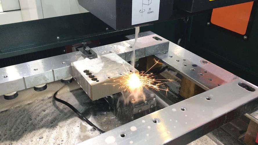
In CNC drilling, feeds and speeds are the two most critical parameters—their balance determines whether you achieve fast, high-quality results or costly failures (e.g., broken tools, poor hole finish).
- Cutting Speed (Vc): The linear speed of the tool’s cutting edge relative to the workpiece (measured in m/min or ft/min). It controls how fast the tool “cuts” through material and directly impacts heat generation.
- Spindle Speed (S): The rotational speed of the tool (measured in r/min). It is derived from cutting speed and tool diameter (not set arbitrarily).
- Feed Rate (F): The linear speed at which the tool advances into the workpiece (measured in mm/min or ipm). It controls material removal rate and chip formation.
Why they matter:
- Tool Life: A 20% increase in cutting speed can reduce carbide tool life by 50% (Source: 2025 CNC Tool Wear Study).
- Hole Quality: Too slow a feed rate causes “rubbing” (cloudy holes in acrylic); too fast causes chipping (in aluminum) or tool breakage (in steel).
- Efficiency: Optimized feeds/speeds cut cycle time by 30-40% vs. “safe” (overly slow) parameters—critical for high-volume production.
2. Key Fundamentals: Calculating Feeds and Speeds
You cannot rely on “guesswork”—feeds and speeds are calculated using material properties, tool type, and hole requirements. Below are the foundational formulas and steps.
A. Step 1: Calculate Spindle Speed (S) from Cutting Speed (Vc)
Spindle speed depends on cutting speed (Vc) (material-specific) and tool diameter (D). The formula (metric units) is:
S (r/min) = (1000 × Vc) / (π × D)
- 1000: Converts mm to meters (since Vc is in m/min).
- π × D: Circumference of the tool (distance the cutting edge travels per revolution).
Example: Drilling 45# steel (Vc = 120 m/min) with a φ8mm carbide drill:
S = (1000 × 120) / (3.14 × 8) ≈ 4775 r/min (round to 4800 r/min for practical use).
B. Step 2: Calculate Feed Rate (F)
Feed rate depends on spindle speed (S), feed per tooth (fz) (tool/material-specific), and number of flutes (Z) (for multi-flute tools like end mills). For standard twist drills (2 flutes), the formula simplifies to:
F (mm/min) = S × fz × Z
- fz: Feed per tooth (mm/tooth) — the amount of material each flute removes per revolution (varies by material and tool).
Example: Same 45# steel + φ8mm carbide drill (fz = 0.1 mm/tooth, Z = 2):
F = 4800 × 0.1 × 2 = 960 mm/min (round to 950 mm/min for stability).
C. Critical Variables That Impact Calculations
Do not use “one-size-fits-all” values—adjust for these factors:
|
Variable
|
Impact on Feeds/Speeds
|
|
Material Hardness
|
Harder materials (e.g., 7075 aluminum, 4140 steel) require lower Vc (reduce by 20-30%).
|
|
Tool Material
|
Carbide tools handle 2-3× higher Vc than HSS (e.g., Vc=120 m/min for carbide vs. 40 m/min for HSS in steel).
|
|
Hole Depth
|
Deep holes (>5×D) need 10-15% lower F (to improve chip evacuation and reduce tool stress).
|
|
Workpiece Rigidity
|
Thin/wobbly parts (e.g., 1mm aluminum sheets) need 15-20% lower S and F (prevent vibration).
|
3. Material-Specific Feeds and Speeds (Practical Reference Tables)
The biggest mistake is using the same parameters for steel, aluminum, and acrylic. Below are optimized values for the most common materials and tool types (metric units).
A. Steel & Stainless Steel (Hard Materials)
|
Material
|
Tool Type
|
Tool Diameter (D)
|
Cutting Speed (Vc)
|
Spindle Speed (S)
|
Feed per Tooth (fz)
|
Feed Rate (F)
|
|
45# Steel (HB200)
|
Carbide Twist Drill
|
φ5mm
|
100-120 m/min
|
6369-7643 r/min
|
0.08-0.10 mm/tooth
|
509-764 mm/min
|
|
45# Steel (HB200)
|
HSS Twist Drill
|
φ5mm
|
30-40 m/min
|
1909-2546 r/min
|
0.05-0.07 mm/tooth
|
95-178 mm/min
|
|
304 Stainless Steel
|
Carbide Twist Drill
|
φ5mm
|
60-80 m/min
|
3819-5092 r/min
|
0.06-0.08 mm/tooth
|
229-407 mm/min
|
Key Tip: Stainless steel (304) work-hardens—use a “higher Vc + lower fz” strategy to avoid dulling tools.
B. Aluminum Alloys (Soft, High Thermal Conductivity)
|
Material
|
Tool Type
|
Tool Diameter (D)
|
Cutting Speed (Vc)
|
Spindle Speed (S)
|
Feed per Tooth (fz)
|
Feed Rate (F)
|
|
6061-T6 Aluminum
|
Carbide Twist Drill
|
φ5mm
|
300-400 m/min
|
19098-25464 r/min
|
0.15-0.20 mm/tooth
|
5729-10185 mm/min
|
|
7075-T6 Aluminum
|
Carbide Twist Drill
|
φ5mm
|
200-250 m/min
|
12732-15915 r/min
|
0.12-0.15 mm/tooth
|
3055-4774 mm/min
|
|
6061-T6 Aluminum
|
HSS Twist Drill
|
φ5mm
|
100-120 m/min
|
6369-7643 r/min
|
0.10-0.12 mm/tooth
|
1273-1834 mm/min
|
Key Tip: Aluminum chips are “stringy”—use a higher feed rate (fz=0.15-0.20) to break chips into small pieces.
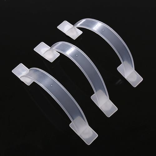
C. Plastics (Acrylic, PVC—Low Melting Point)
|
Material
|
Tool Type
|
Tool Diameter (D)
|
Cutting Speed (Vc)
|
Spindle Speed (S)
|
Feed per Tooth (fz)
|
Feed Rate (F)
|
|
Acrylic (PMMA)
|
Single-Flute Carbide
|
φ5mm
|
150-200 m/min
|
9549-12732 r/min
|
0.20-0.25 mm/tooth*
|
3819-6366 mm/min
|
|
PVC
|
Carbide Twist Drill
|
φ5mm
|
120-150 m/min
|
7643-9549 r/min
|
0.18-0.22 mm/tooth
|
2751-4191 mm/min
|
Note: For single-flute tools (acrylic), Z=1—so F = S × fz × 1 (simplified formula).
4. Practical Case: Optimizing Feeds/Speeds for Drilling 45# Steel (φ8mm Hole)
Let’s apply the formulas and tables to a real-world scenario—drilling a 10mm-deep φ8mm through-hole in 45# steel (HB200) with a carbide twist drill.
Step 1: Define Requirements
- Material: 45# steel (Vc = 120 m/min, from Table A).
- Tool: φ8mm carbide twist drill (Z=2 flutes, fz=0.10 mm/tooth).
- Hole Depth: 10mm (≤5×D, so no need to reduce F).
Step 2: Calculate Spindle Speed (S)
S = (1000 × Vc) / (π × D) = (1000 × 120) / (3.14 × 8) ≈ 4775 r/min → Set to 4800 r/min.
Step 3: Calculate Feed Rate (F)
F = S × fz × Z = 4800 × 0.10 × 2 = 960 mm/min → Set to 950 mm/min (for stability).
Step 4: Program Snippet (FANUC System)
O0007 (45# Steel Drilling Program: φ8mm Hole)
G90 G54 G00 X50 Y50 Z15 // Absolute mode, G54, safe height
M03 S4800 // Spindle speed = 4800 r/min (calculated)
M08 // Coolant on (emulsified coolant for steel)
// Drill cycle with optimized F
G81 X50 Y50 Z-12 R2 F950 // F=950 mm/min (calculated), Z-12=10mm depth + 2mm overcut
G80
// Program End
G00 X0 Y0 Z50
M05 M09
M30
Step 5: Verify Results
- Tool Life: Carbide drill lasts 800+ holes (vs. 500 holes with under-speeding).
- Hole Quality: Diameter tolerance H8 (φ8+0.013/0), surface roughness Ra=1.6μm.
- Cycle Time: 2.1 seconds/hole (vs. 3.5 seconds with “safe” parameters).
5. Common Feeds/Speeds Mistakes & Solutions
Even with calculations, errors happen. Below are the most frequent issues and how to fix them.
1. Tool Breaks Immediately (Steel/Aluminum)
- Cause: Feed rate too high (exceeds tool’s load capacity) or spindle speed too low (tool “binds” in material).
- Solution:
-
- Reduce F by 30% (e.g., from 950 mm/min to 665 mm/min for 45# steel).
-
- Increase S by 10% (e.g., from 4800 r/min to 5280 r/min) to improve cutting efficiency.
2. Tool Wear Fast (Stainless Steel/7075 Aluminum)
- Cause: Cutting speed too high (generates excess heat) or feed rate too low (tool rubs, not cuts).
- Solution:
-
- Reduce Vc by 20% (e.g., from 80 m/min to 64 m/min for 304 stainless steel).
-
- Increase fz by 10% (e.g., from 0.08 mm/tooth to 0.088 mm/tooth) to promote “chip lifting” (reduces friction).
3. Cloudy Holes (Acrylic/PVC)
- Cause: Cutting speed too low (tool dwells, melts plastic) or feed rate too slow (rubbing, not cutting).
- Solution:
-
- Increase S by 20% (e.g., from 9500 r/min to 11400 r/min for acrylic).
-
- Increase F by 15% (e.g., from 3800 mm/min to 4370 mm/min) to reduce contact time.
4. Chipping at Hole Exit (Aluminum/Thin Steel)
- Cause: Feed rate too high (excessive force on exit) or no pilot hole.
- Solution:
-
- Reduce F by 20% in the last 2mm of depth (use G91 incremental mode: G91 G01 Z-2 F760).
-
- Drill a pilot hole (φ4mm for φ8mm final hole) to reduce exit force.
6. Q&A: High-Frequency Feeds/Speeds Questions
Q1: I don’t have time to calculate—what’s a “quick reference” for beginners?
- Use these “rule-of-thumb” Vc values (carbide tools):
-
- Steel: 100-120 m/min.
-
- Aluminum: 300-400 m/min.
-
- Acrylic: 150-200 m/min.
- Then use a CNC calculator app (e.g., “CNC Feeds and Speeds Calculator”) to auto-generate S and F.
Q2: How to adjust feeds/speeds for deep holes (>10×D, e.g., φ5mm×60mm)?
- Cutting Speed: Reduce Vc by 10% (avoids heat buildup in deep holes).
- Feed Rate: Reduce F by 15-20% (improves chip evacuation—use peck drilling G83 with Q=3-4mm).
- Coolant: Use high-pressure internal coolant (5-8 bar) to flush chips.
Q3: Why do feeds/speeds differ for HSS vs. carbide tools?
- Carbide has a higher melting point (2800°C vs. 1400°C for HSS) and hardness (HRC90+ vs. HRC60-65 for HSS). This allows carbide to handle 2-3× higher Vc—critical for efficiency.
- HSS is cheaper but softer: Use lower Vc (30-50% of carbide) to avoid rapid dulling.
Final Thought
CNC drilling feeds and speeds are not “fixed numbers”—they are a dynamic balance of material, tool, and hole requirements. The worst approach is using “safe” (overly slow) parameters—you waste time and money on tool life and cycle time. Instead, start with calculated values, test on scrap material, and tweak based on results (e.g., if the tool is hot, reduce Vc; if chips are too fine, increase F).
Have you struggled with broken tools or poor hole finish due to feeds/speeds? Or need help optimizing parameters for a specific material (e.g., titanium, wood)? Share your scenario in the comments—I’ll provide tailored calculations!