Table of Contents
- Overall Equipment Structure Design
- Spindle System Core Technology
- Feed Drive System
- Tool Magazine and Automatic Tool Changer
- Control System and Programming Technology
- Precision Control and Measurement
- Cooling and Lubrication System
- Safety Protection Design
- Maintenance and Service Technology
- Application Fields and Technical Advantages
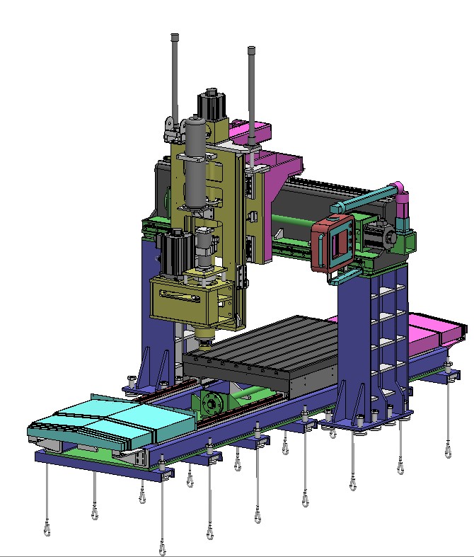
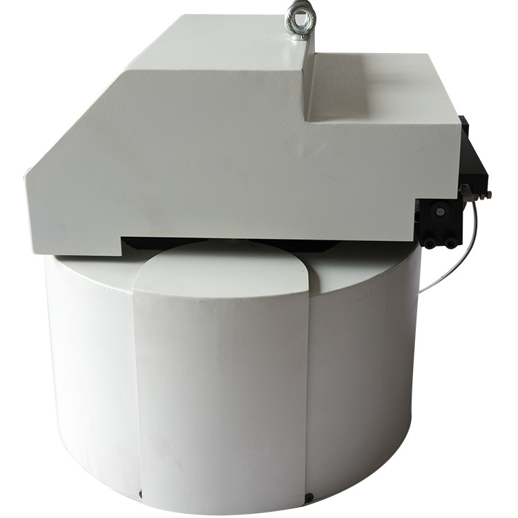
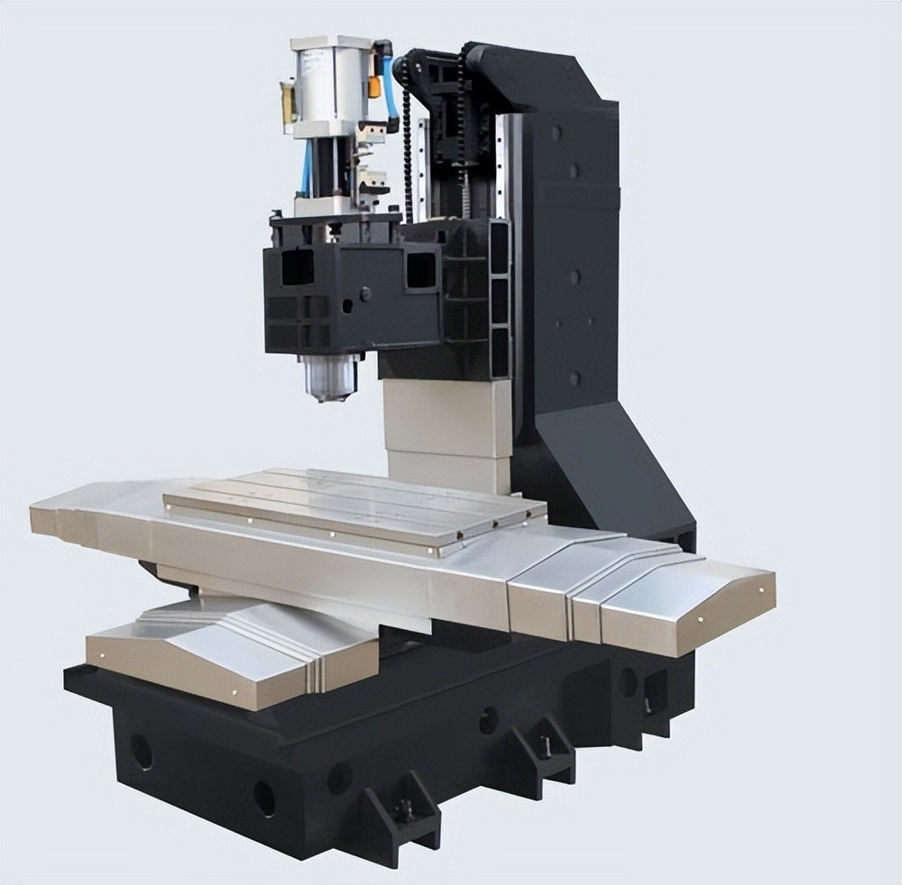
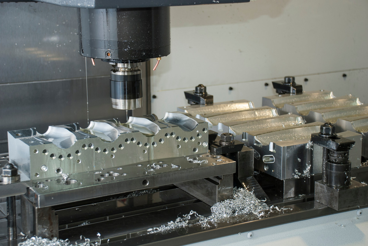
Overall Equipment Structure Design
CNC machining centers are highly automated multi-functional machine tools that integrate milling, drilling, boring, and other machining capabilities. The overall structural design directly impacts machining precision, stability, and efficiency.
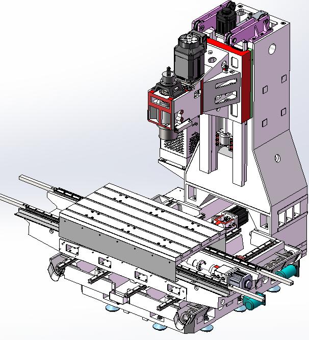
Main Components:
- Machine Base – Provides stable foundation support, constructed from high-strength cast iron or granite materials
- Column – Supports the spindle head, requiring excellent rigidity and vibration resistance
- Spindle Head – Houses the spindle assembly, enabling rotational movement of the spindle
- Worktable – Carries the workpiece, achieve ing X, Y, Z axis feed movements
- Tool Magazine – Stores and manages cutting tools, supporting automatic tool changing functionality
- Control System – Implements digital control of the machining process
Structural Design Features:
- Rigid Design – Optimized using finite element analysis to ensure machining stability
- Thermal Symmetric Design – Reduces the impact of temperature changes on precision
- Modular Design – Facilitates maintenance and functional expansion
- Ergonomic Design – Optimized operator interface and maintenance access
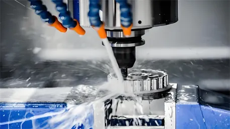
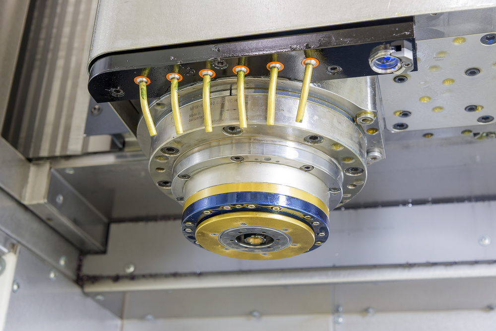
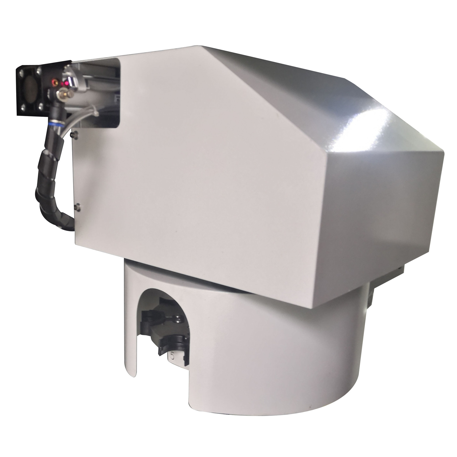
Spindle System Core Technology
The spindle system is the core component of a CNC machining center, directly determining machining precision and efficiency. Modern machining center spindles incorporate multiple advanced technologies.
Spindle Technical Parameters:
|
Parameter Item
|
Technical Specification
|
Technical Features
|
|
Spindle Speed
|
8000-15000 RPM
|
Variable frequency control, constant power output
|
|
Spindle Taper
|
BT40/BT50
|
High-precision taper 配合
|
|
Spindle Motor Power
|
7.5-22 kW
|
Direct servo motor drive
|
|
Axial/Radial Runout
|
≤0.003mm
|
High-precision bearing support
|
Key Spindle System Technologies:
- High-Precision Bearings – Utilizing ceramic bearings or precision angular contact ball bearings
- Oil Mist Lubrication – Ensuring proper lubrication and cooling of bearings at high speeds
- Spindle Temperature Control – Active temperature control system maintains stable spindle temperature
- Dynamic Balancing Technology – Reduces vibration during high-speed rotation
Spindle Drive Methods:
- Belt Drive – Suitable for medium-low speed spindles, cost-effective
- Direct Drive – Motor directly drives the spindle, high transmission precision
- Motorized Spindle – Motor rotor integrated with spindle, speeds up to 40000 RPM
Feed Drive System
The feed system is responsible for achieving precise movement of the worktable and is a critical component ensuring machining accuracy. Modern CNC machining centers employ servo drive technology.
Feed System Components:
- Servo Motor – Provides power output, utilizing AC servo motors
- Ball Screw – Converts rotational motion to linear motion
- Guideway System – Ensures motion precision and stability
- Position Detection – Real-time position feedback
Technical Features:
- High-Precision Ball Screws – Pitch error compensation, positioning accuracy up to ±0.005mm
- Linear Guideways – Low friction coefficient, smooth motion
- Servo Control System – Achieves precise control of position, speed, and torque
- Dynamic Error Compensation – Real-time compensation of motion errors
Feed Parameter Comparison:
|
Axis
|
Rapid Traverse Speed
|
Feed Rate
|
Positioning Accuracy
|
|
X-axis
|
30-48 m/min
|
1-24 m/min
|
±0.003mm
|
|
Y-axis
|
30-48 m/min
|
1-24 m/min
|
±0.003mm
|
|
Z-axis
|
24-36 m/min
|
1-18 m/min
|
±0.003mm
|
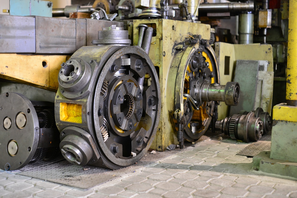
Tool Magazine and Automatic Tool Changer
The automatic tool changing system is an important functional module of CNC machining centers, directly impacting machining efficiency and automation levels.
Tool Magazine Types and Features:
1. Turret-Type Tool Magazine
- Capacity: 16-24 tools
- Tool Change Time: 8-12 seconds
- Structural Features: Simple structure, cost-effective
- Application: Small to medium batch production
2. Disc-Type Tool Magazine
- Capacity: 20-40 tools
- Tool Change Time: 6-8 seconds
- Structural Features: Compact footprint, fast tool change
- Application: Medium batch production
3. Chain-Type Tool Magazine
- Capacity: 40-120 tools
- Tool Change Time: 12-15 seconds
- Structural Features: Large capacity, expandable
- Application: Large batch complex part machining
Tool Changing Mechanism Technology:
- Robot Arm Tool Change – Cam or hydraulic driven, precise movement
- Tool Position Detection – Photoelectric sensors confirm tool position
- Tool Identification – RFID or encoder disc for tool information
- Automatic Tool Length Compensation – Tool length measurement and compensation
Tool Management Functions:
- Tool Life Management – Monitors tool usage time and cutting cycles
- Tool Breakage Detection – Real-time tool condition monitoring
- Tool Presetting – Offline tool parameter setting
- Tool Change Optimization – Optimizes tool change sequence to reduce time
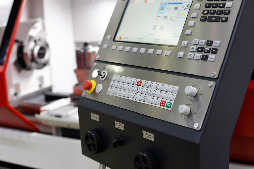
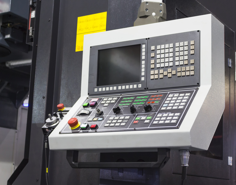
Control System and Programming Technology
The CNC control system serves as the “brain” of the machining center, responsible for interpreting machining instructions and coordinating the operation of various components.
Mainstream Control Systems:
1. Fanuc Series 0i-MF
- Control Axes: Up to 6-axis simultaneous control
- Program Storage: 32MB memory, expandable to 2GB
- Special Features: AI contour control, high-speed high-precision machining
- User Interface: Color LCD display, user-friendly operation
2. Siemens SINUMERIK 828D
- Control Axes: Up to 5-axis simultaneous control
- Programming Method: ShopMill/ShopTurn conversational programming
- Special Features: 3D simulation, collision detection
- Network Functionality: Industrial Ethernet support
3. Mitsubishi M80
- Control Axes: Up to 8-axis simultaneous control
- Processing Speed: 32-bit RISC processor
- Special Features: High-speed look-ahead control
- Communication Interfaces: USB, Ethernet, RS232
Programming Technologies:
- G-code Programming – Standard CNC programming language
- M-code Programming – Auxiliary function control
- Macro Programming – Custom cycle programs
- CAD/CAM Integration – Computer-aided programming
Advanced Control Features:
- High-Speed Look-Ahead – Preprocessing of machining paths
- Adaptive Control – Adjusts feed rate based on cutting load
- Error Compensation – Geometric error and thermal error compensation
- Remote Monitoring – Real-time equipment status monitoring
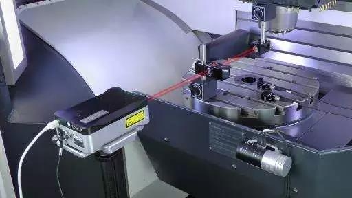
Precision Control and Measurement
Machining precision is a core indicator of CNC machining centers, involving multiple precision control and measurement technologies.
Precision Classification and Specifications:
1. Geometric Precision
- Positioning Accuracy: ±0.003-±0.005mm
- Repeatability: ±0.002-±0.003mm
- Straightness: 0.002mm/m
- Perpendicularity: 0.002mm/m
2. Motion Precision
- Circular Interpolation Accuracy: ±0.003mm
- Thread Machining Accuracy: ISO 4H/5g
- Surface Roughness: Ra 0.8-3.2μm
3. Machining Precision
- Dimensional Accuracy: IT5-IT7 grade
- Geometric Tolerances: 0.005-0.01mm
- Surface Quality: Mirror finish achievable
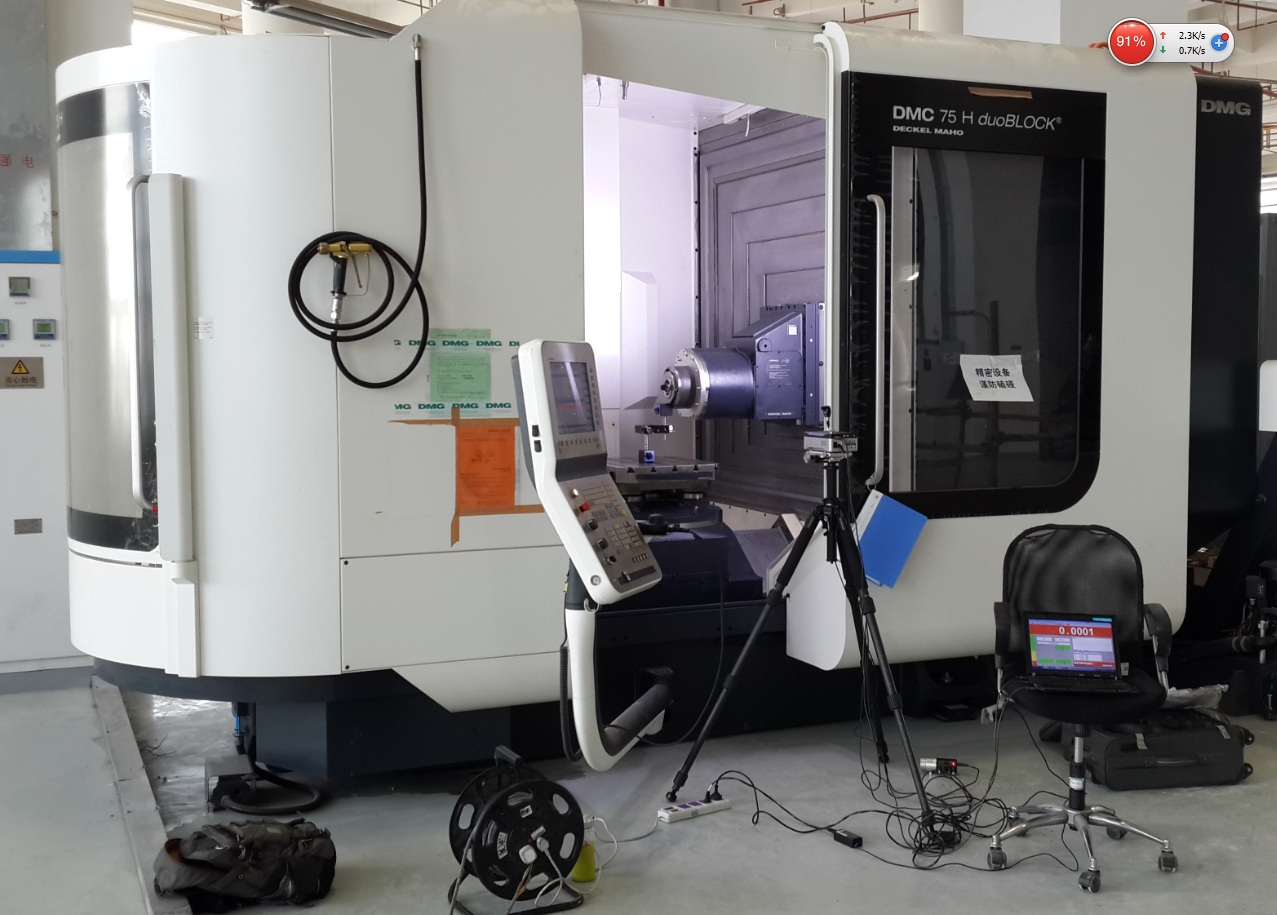
Precision Measurement Technologies:
- Laser Interferometer – Measures positioning accuracy and geometric errors
- Ballbar Testing – Evaluates dynamic accuracy and servo performance
- Coordinate Measuring Machine (CMM) – Verifies final workpiece accuracy
- In-Process Measurement – Real-time precision monitoring during machining
Precision Assurance Measures:
- Temperature Control – Workshop temperature maintained at 20±2°C
- Vibration Isolation – Anti-vibration foundations and damping measures
- Error Compensation – Geometric, thermal, and load error compensation
- Regular Calibration – Precision calibration according to standards
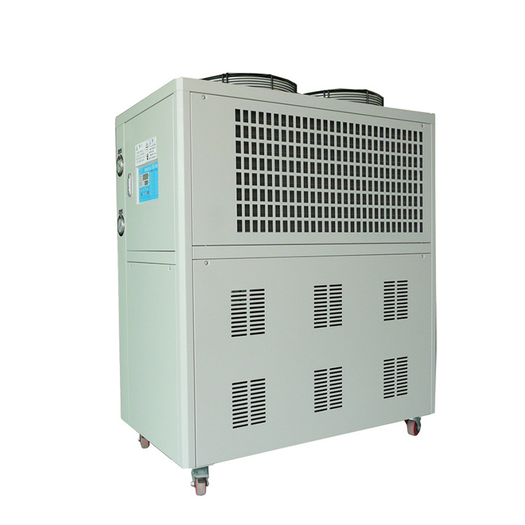
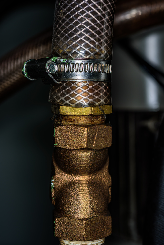
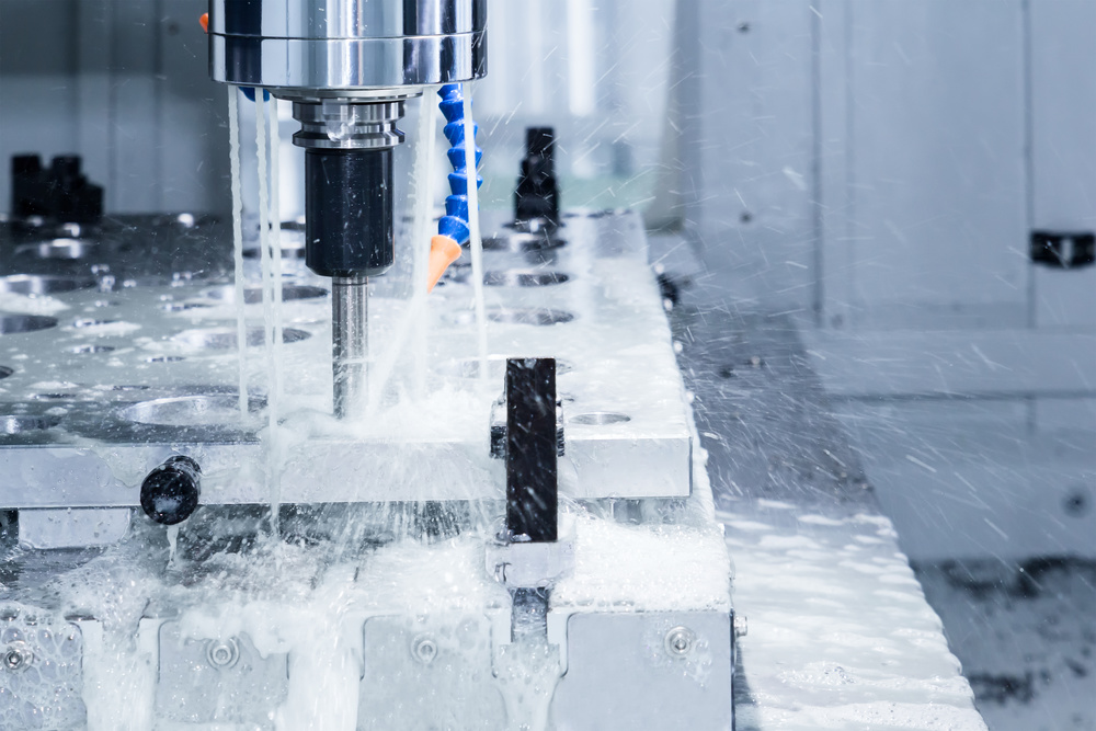
Cooling and Lubrication System
The cooling and lubrication system is crucial for the proper operation and machining quality of the machining center.
Cooling System Types:
1. Cutting Fluid Cooling System
- Function: Cools tools and workpiece, flushes away chips
- Types: Emulsions, synthetic coolants, oil-based cutting fluids
- Circulation Method: Pump circulation, filtration precision 20-50μm
- Cooling Capacity: 5-20kW cooling capacity
2. Spindle Cooling System
- Cooling Method: Oil or water cooling
- Temperature Control Precision: ±1°C
- Flow Control: Automatic adjustment based on spindle load
- Heat Dissipation Capacity: Matches spindle power requirements
3. Machine Cooling System
- Cooling Objects: Electrical cabinet, servo motors, ball screws
- Cooling Method: Air or liquid cooling
- Temperature Control: Maintains stable operating temperature
- Energy-Saving Design: Intelligent temperature control, on-demand cooling
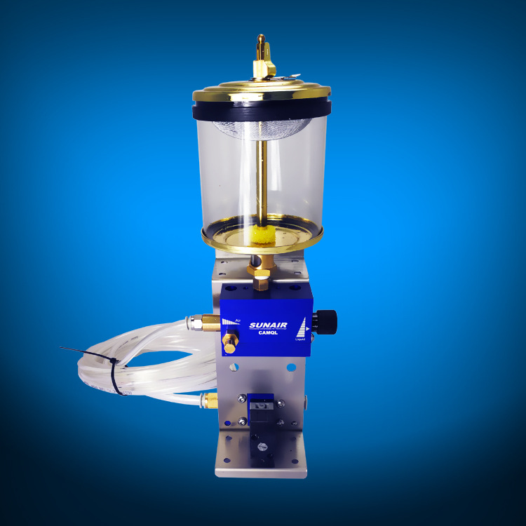
Lubrication System:
- Lubrication Methods: Oil-air lubrication, grease lubrication
- Lubrication Points: Ball screws, guideways, spindle bearings
- Lubrication Cycle: Programmable automatic lubrication
- Condition Monitoring: Real-time monitoring of lubrication system status
System Features:
- Intelligent Control – Automatic adjustment based on machining conditions
- Energy Efficiency – Optimized cooling and lubrication parameters, reduced energy consumption
- Maintenance-Friendly – Modular design for easy maintenance
- Environmental Compliance – Meets environmental protection standards
Safety Protection Design
The safety protection design of CNC machining centers ensures operator safety and proper equipment operation.
Safety Protection System Components:
1. Mechanical Protection
- Safety Doors – Interlock protection, machine stops when door opens
- Protective Covers – Prevent chip and coolant splashing
- Emergency Stop Buttons – Rapid machine shutdown in emergency situations
- Safety Locks – Prevent unauthorized operation
2. Electrical Safety
- Overload Protection – Motor overload and short circuit protection
- Earth Leakage Protection – Protection against electrical equipment leakage
- Overvoltage Protection – Voltage anomaly protection
- EMC Protection – Electromagnetic compatibility protection
3. Control System Safety
- Program Protection – Machining program password protection
- Operation Permissions – Multi-level user permission management
- Error Detection – Program error and operation error detection
- Emergency Stop – Multiple emergency stop circuits
Safety Standards and Certifications:
- ISO 13849 – Machinery safety standard
- IEC 61508 – Functional safety standard
- CE Certification – European safety certification
- OSHA Standards – American occupational safety standards
Safety Monitoring Functions:
- Area Monitoring – Hazardous area intrusion detection
- Status Display – Real-time display of equipment operating status
- Alarm System – Fault and abnormal condition alarms
- Log Recording – Safety event and operation logging
Maintenance and Service Technology
Regular maintenance is crucial for ensuring the long-term stable operation of CNC machining centers.
**
Maintenance Classification:
1. Daily Maintenance
- Cleaning – Equipment exterior and work area cleaning
- Lubrication Check – Lubrication system oil level and quality inspection
- Cooling System – Coolant level and concentration check
- Air Pressure System – Air pressure and leakage inspection
2. Periodic Maintenance
Weekly Maintenance:
- Guideway and ball screw cleaning and lubrication
- Filter inspection and cleaning
- Electrical cabinet cooling inspection
- Safety device function check
Monthly Maintenance:
- Spindle system condition inspection
- Servo motor temperature check
- Hydraulic system pressure inspection
- Tool clamping system check
Quarterly Maintenance:
- Precision measurement and calibration
- Transmission system backlash inspection
- Electrical system insulation test
- Software backup and updates
3. Annual Maintenance
- Comprehensive precision measurement and adjustment
- Spindle bearing condition assessment
- Servo system performance testing
- Control system function check
Maintenance Schedule:
|
Maintenance Interval
|
Maintenance Item
|
Maintenance Content
|
Responsible Person
|
|
Daily
|
Routine Inspection
|
Cleaning, lubrication, level checks
|
Operator
|
|
Weekly
|
Regular Inspection
|
Guideway lubrication, filter cleaning
|
Technician
|
|
Monthly
|
In-depth Inspection
|
Spindle inspection, hydraulic system
|
Engineer
|
|
Annual
|
Comprehensive Maintenance
|
Precision calibration, system testing
|
Professional Service
|
Fault Diagnosis and Troubleshooting:
- Fault Codes – System fault code analysis
- Condition Monitoring – Equipment operating status monitoring
- Diagnostic Tools – Specialized diagnostic software and tools
- Spare Parts Management – Critical spare parts inventory management
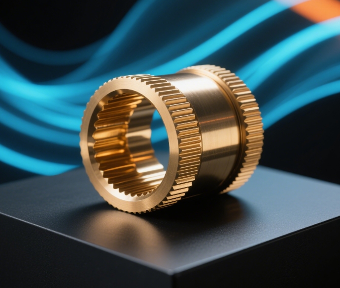
Application Fields and Technical Advantages
CNC machining centers are widely used in various manufacturing fields, offering significant technical advantages.
Main Application Fields:
1. Aerospace Manufacturing
- Application Components: Engine parts, structural components, landing gear parts
- Technical Requirements: High precision, high reliability, complex shapes
- Material Processing: Titanium alloys, aluminum alloys, high-temperature alloys
- Quality Standards: AS9100 certification, strict quality control
2. Automotive Manufacturing
- Application Components: Engine blocks, transmission parts, chassis components
- Technical Requirements: High volume, high efficiency, good consistency
- Production Features: High automation, flexible manufacturing
- Quality Standards: IATF16949 certification
3. Medical Device Manufacturing
- Application Components: Surgical instruments, implants, medical equipment parts
- Technical Requirements: Ultra-high precision, excellent surface quality, biocompatibility
- Material Requirements: Titanium alloys, stainless steel, ceramic materials
- Quality Standards: ISO13485 certification
4. Mold Manufacturing
- Application Components: Plastic molds, stamping dies, die casting molds
- Technical Requirements: Complex surface machining, high precision, surface quality
- Processing Features: Single-piece small batch, high customization
- Technical Challenges: Deep cavity machining, micro-machining
Technical Advantages:
- High-Precision Machining – Positioning accuracy up to ±0.003mm
- High-Efficiency Production – Automatic tool change, reduced auxiliary time
- Flexible Manufacturing – Rapid changeover, adaptable to multiple product types
- Complex Shape Machining – Multi-axis simultaneous machining of complex surfaces
- High Automation Level – Enables unmanned production
- Stable Quality – Consistent machining quality and reliability
Economic Analysis:
- Production Efficiency – 3-5 times improvement compared to traditional machines
- Labor Costs – Reduced labor requirements, lower labor costs
- Quality Costs – Reduced scrap rates, lower quality costs
- Return on Investment – Typically 2-3 year payback period
Summary and Future Outlook
CNC machining centers, as core equipment in modern manufacturing, integrate mechanical, electrical, hydraulic, pneumatic, and computer control technologies. Their technological development trends are mainly reflected in:
Technology Development Trends:
- Higher Precision – Positioning accuracy moving toward nanometer level
- Higher Speed – Continued increase in spindle speeds and feed rates
- Intelligentization – Integration of AI technology for adaptive machining
- Green Technology – Continuous improvement of energy-saving and environmental protection technologies
- Integration – Deep integration with CAD/CAM systems
- Networking – Implementation of factory network management
Future Development Directions:
- 5-Axis Machining Technology – Complex parts completed in single setup
- Additive Manufacturing Integration – Combination of CNC machining with 3D printing technology
- Digital Twin Technology – Synchronization of virtual simulation with actual machining
- Industry 4.0 Integration – Core component of smart factories
Continuous advancement in CNC machining center technology will continue to drive manufacturing toward higher precision, higher efficiency, and greater intelligence, providing better manufacturing solutions for various industries.
Technical References:
- ISO 230-1:2012 – Test code for machine tools
- ISO 10791-1:2014 – CNC milling machines
- GB/T 18400.1-2010 – Machine tools safety standards
- DIN 8603 – Accuracy of machine tools
Document Version: 1.0