I. Overview of Aerospace CNC Machining
In the modern aerospace industry, CNC (Computer Numerical Control) machining technology has become the core means of manufacturing high – precision and high – performance components. With the continuous advancement of aerospace technology, higher requirements are put forward for the design and processing of components, and traditional processing methods can no longer meet these needs. CNC machining technology, with its characteristics of high precision, high efficiency, and high automation, has become the key technology to solve this problem.
1.1 Importance of CNC Machining in the Aerospace Field
The manufacturing of aerospace components has extremely strict requirements for precision, reliability, and consistency. CNC machining technology can meet these stringent standards, ensuring that each component can operate safely and reliably in extreme environments. Through computer control, CNC machine tools can achieve precise machining of complex curved surfaces, which is particularly important in the aerospace field. Components of aircraft, such as wings, fuselages, and engine parts, often have complex geometric shapes. Traditional processing methods require a large amount of labor and time. However, CNC machining can complete high – precision machining tasks in a short time, greatly improving production efficiency.
1.2 Technical Characteristics of Aerospace CNC Machining
The main characteristics of aerospace CNC machining are high precision, high efficiency, and high reliability. The precision of CNC machine tools can reach several microns, with a very small error range. This high precision ensures the precise fit of aerospace components, thus preventing overall failures and property losses.
In the aerospace field, CNC machining usually adopts multi – axis linkage technology, especially 5 – axis CNC machining, which can machine at multiple angles simultaneously, enabling the processing of more complex curved surfaces. This technology not only improves machining precision but also reduces the fixture change time of workpieces, further enhancing production efficiency. In addition, CNC machining has the characteristics of high automation and strong repeatability, ensuring consistent quality of components in mass production.
1.3 Development Trends of Aerospace CNC Machining
With the continuous progress of technology, aerospace CNC machining is developing in the following directions:
Intelligent Development: With the continuous development of artificial intelligence and big data technology, CNC technology will become more intelligent, capable of automatically optimizing the machining process and further improving machining precision and efficiency.
Higher – Precision Machining: With the progress of materials and processes, CNC technology will be able to achieve higher – precision machining to meet the increasing demand for higher – precision components in the aerospace industry.
Improvement of Composite Material Processing Technology: With the widespread application of composite materials in the aerospace industry, CNC technology will further optimize its processing capabilities for composite materials, improving processing quality and efficiency.
Green Manufacturing: The application of environmentally friendly materials and energy management will become an important development direction of aerospace CNC machining to achieve green production.
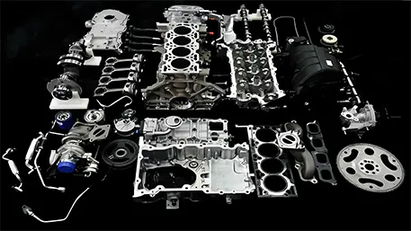
II. CNC Machining of Aerospace Engine Components
The aerospace engine is the “heart” of an aircraft, and the processing quality of its components is directly related to the performance and safety of the aircraft. Engine components usually work in extreme environments of high temperature, high pressure, and high – speed rotation, so there are extremely high requirements for materials and processing precision.
2.1 Main Types and Materials of Engine Components
Aerospace engine components mainly include turbine blades, compressor disks, combustion chamber casings, and nozzles. These components are usually made of high – strength materials such as superalloys or titanium alloys, requiring extremely high precision and surface quality.
Commonly used materials include:
Superalloys: Such as nickel – based alloys, which have excellent high – temperature strength and oxidation resistance.
Titanium Alloys: They have high strength, low density, and good corrosion resistance.
Special Steels: Such as martensitic stainless steels, which have high strength and good toughness.
Take the combustion chamber casing as an example. It is an important functional component at the hot end of a certain type of aerospace engine. It is a typical thin – walled ring – shaped part. The large – end diameter is about Φ600mm, the small – end diameter is about Φ420mm, the total height is about 290mm, and the wall thickness is 4.5mm. The workpiece material is 13Cr11Ni2W2MoV martensitic stainless steel, with a hardness of HB311 – 388, and its thermal conductivity is close to that of nickel – based superalloys.
2.2 CNC Machining Process and Flow of Engine Components
The CNC machining of aerospace engine components usually adopts multi – axis linkage machining technology, especially 5 – axis CNC machining, which can achieve precise machining of complex curved surfaces. The following is the typical processing flow of engine components:
Blank Preparation: Prepare suitable material blanks according to design requirements. Usually, forging or casting methods are used to obtain blanks close to the final shape.
Rough Machining: Use CNC machine tools for preliminary processing, removing most of the allowance and leaving an appropriate allowance for subsequent finish machining. In the rough – machining stage, whisker – reinforced ceramic turning inserts are used to quickly remove large amounts of material.
Heat Treatment: Conduct appropriate heat treatment according to material characteristics, such as quenching and tempering, to achieve the required hardness and mechanical properties.
Semi – finish Machining: Perform preliminary shaping of the blades on a GROB 350 five – axis machining center, getting closer to the final shape.
Finish Machining: Use high – precision CNC machine tools for final processing to achieve the dimensional accuracy and surface quality required by the design. Finish machining is carried out by milling with a Φ12R3 bull – nose cutter + finishing the surface with a Φ6 ball – nose cutter.
Surface Treatment: Conduct surface treatment as required, such as coating, nitriding, etc., to improve the wear resistance, corrosion resistance, and high – temperature performance of the components.
Quality Inspection: Use precision measuring equipment such as a coordinate measuring machine (CMM) to comprehensively inspect the processed components to ensure they meet the design requirements.
Take the processing of turbine blades as an example. The processing flow adopted by WayKen includes: chemical composition inspection (using an Olympus Vanta Element – S X – ray fluorescence spectrometer to analyze the chemical composition of the blank to ensure it meets the material standard), semi – finish machining (performing preliminary shaping of the blades on a GROB 350 five – axis machining center), and finish machining (achieving the final dimensions and surface quality requirements).
2.3 Key Technical Parameters of Engine Components
The machining of aerospace engine components requires controlling multiple key technical parameters to ensure their performance and reliability:
Dimensional Accuracy: The dimensional accuracy of aerospace engine components usually requires an error range within ±0.005mm or even higher. For some key parts, such as the clearance between the blade tip of the turbine blade and the casing, it is controlled within a very small range to improve engine efficiency.
Surface Roughness: The surface roughness requirement of engine components is extremely high, usually requiring Ra 0.8μm or lower, and some parts even require Ra 0.4μm or higher. A smooth surface can reduce air flow resistance and improve engine efficiency.
Form and Position Tolerance: Including roundness, cylindricity, flatness, perpendicularity, coaxiality, etc., usually requires control within 0.01mm.
Hardness: Depending on the material and the part’s application, the hardness requirements of engine components vary. For example, the hardness requirement of 13Cr11Ni2W2MoV martensitic stainless steel is HB311 – 388.
Machining Allowance: Leave an allowance of 0.5 – 1mm after rough machining and 0.1 – 0.3mm after semi – finish machining to ensure the accuracy of finish machining.
2.4 Common Problems and Solutions in Engine Component Machining
During the CNC machining of engine components, the following technical challenges are often faced:
Difficulty in Material Machining: Materials such as superalloys and titanium alloys have characteristics such as high strength, high hardness, and low thermal conductivity. During machining, problems such as high cutting force, high cutting temperature, and rapid tool wear are likely to occur.
Select appropriate tool materials, such as carbide tools, ceramic tools, or CBN tools.
Adopt advanced tool coating technologies, such as PVD coating, to improve tool wear resistance and lubricity.
Optimize cutting parameters, adopting a processing strategy of low feed rate and high cutting speed.
Use a high – pressure cooling system to effectively reduce cutting temperature and improve chip removal.
Solutions:
Thin – Wall Deformation Problem: Components such as combustion chamber casings are thin – wall structures and are prone to deformation during machining, affecting dimensional accuracy and form – position tolerance.
Adopt a layered cutting strategy, gradually removing material to reduce cutting force and deformation.
Use auxiliary supports or fixtures to increase workpiece rigidity.
Optimize the machining path to avoid concentrated cutting and excessive cutting load.
Perform stress – relief treatment during machining to reduce residual stress.
Solutions:
Precision Control of Complex Curved – Surface Machining: Components such as turbine blades have complex aerodynamic shapes, and it is difficult to control machining precision.
Adopt 5 – axis linkage machining technology to achieve precise machining of complex curved surfaces.
Use advanced CAM software for tool – path planning and simulation.
Monitor and adjust in real – time during machining.
Use precision measuring equipment for full – size inspection.
Solutions:
Thermal Deformation Control: The heat generated during machining can cause deformation of the workpiece and tool, affecting machining precision.
Use cutting fluids with good cooling performance or low – temperature cooling technology.
Optimize cutting parameters to reduce the generation of cutting heat.
Machine in stages and leave cooling time.
Pre – heat the workpiece before machining to reduce the temperature gradient.
Solutions:
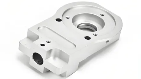
III. CNC Machining of Aerospace Structural Components
Aerospace structural components are the framework of an aircraft, undertaking the important functions of supporting and transmitting loads. The processing quality of structural components directly affects the structural strength and safety of the aircraft.
3.1 Main Types and Materials of Structural Components
Aerospace structural components mainly include wing structural components, fuselage frames, bulkheads, and ribs. These components usually need to bear large loads, so there are high requirements for the strength, stiffness, and lightweight of the materials.
Commonly used structural component materials include:
Aluminum Alloys: Such as 7075 – T6, which has a high strength – to – weight ratio and is widely used in aircraft structural components.
Titanium Alloys: They have high strength, low density, and good corrosion resistance, suitable for high – temperature and high – stress parts.
Composite Materials: Such as carbon – fiber – reinforced plastics (CFRP), which have the characteristics of light weight, high strength, and good fatigue resistance.
High – Strength Steels: They have extremely high strength and toughness, suitable for high – stress parts.
Landing gear structural components are usually made of high – strength steels or titanium alloys. For example, landing gear drag link components are often made of 7075 – T6 aluminum alloy.
3.2 CNC Machining Process and Flow of Structural Components
The CNC machining of aerospace structural components usually adopts 3 – axis, 4 – axis, or 5 – axis linkage machining technology, and the appropriate processing method is selected according to the complexity of the structure. The following is the typical processing flow of structural components:
Design and Programming: Conduct 3D modeling according to the design drawings and use CAM software to generate tool paths and machining programs.
Blank Preparation: Select appropriate material blanks, usually rolled plates, extruded profiles, or forgings.
Positioning and Clamping: Use precision fixtures to fix the blank on the machine tool worktable, ensuring accurate positioning and firm clamping. For large – sized structural components, special support and positioning devices may be required.
Rough Machining: Use large – diameter tools for preliminary processing, removing most of the allowance and leaving an appropriate allowance for subsequent finish machining. Rough machining adopts indexable corn milling cutters for high – depth – of – cut and low – feed – rate heavy – duty cutting.
Semi – finish Machining: Use medium – sized tools for semi – finish machining, getting closer to the final shape and leaving an allowance of 0.2 – 0.5mm for finish machining.
Finish Machining: Use precision tools for final processing to achieve the dimensional accuracy and surface quality required by the design. Finish machining adopts PVD – coated carbide tools for medium – feed – rate milling with small cutting widths and small cutting depths.
Hole Machining: Conduct drilling, reaming, boring, etc. according to design requirements to ensure the position accuracy and dimensional accuracy of the holes.
Surface Treatment: Conduct surface treatment as required, such as anodizing, painting, etc., to improve corrosion resistance and surface quality.
Quality Inspection: Use precision measuring equipment such as a coordinate measuring machine (CMM) to comprehensively inspect the processed structural components to ensure they meet the design requirements.
Take the landing gear drag link component as an example. Its processing process includes: machining from aerospace – grade 7075 – T6 aluminum alloy using a Tormach CNC milling machine. The left and right drag links are composed of inner and outer halves. Each of the four link – half parts is processed with two operation setups. The second operation requires clamping with soft jaws.
3.3 Key Technical Parameters of Structural Components
The machining of aerospace structural components requires controlling multiple key technical parameters to ensure their structural performance and lightweight requirements:
Dimensional Accuracy: The dimensional accuracy of aerospace structural components usually requires control within ±0.05mm, and some key parts require higher accuracy. For precision – positioning holes, higher position accuracy is required, and the coordinate boring process needs to be adopted.
Surface Roughness: The surface roughness of structural components usually requires Ra 1.6 – 3.2μm, and some mating surfaces require higher values.
Flatness and Straightness: The flatness and straightness requirements of structural components are usually in the range of 0.05 – 0.1mm/m to ensure the stability of the structure and assembly accuracy.
Wall – thickness Uniformity: For thin – walled structural components, the requirement for wall – thickness uniformity is very high, usually controlled within ±10% of the designed thickness.
Weight Tolerance: To meet the lightweight requirements of aircraft, the weight tolerance of structural components is usually controlled within ±5%.
Form and Position Tolerance: Including parallelism, perpendicularity, coaxiality, etc., usually requires control within 0.05 – 0.1mm.
3.4 Common Problems and Solutions in Structural Component Machining
During the CNC machining of structural components, the following technical challenges are often faced:
Deformation Control of Large – Sized Structural Components: Large – sized structural components are prone to deformation during machining, affecting dimensional accuracy and form – position tolerance.
Adopt a symmetric machining strategy to balance cutting forces.
Machine in stages to gradually release internal stress.
Use auxiliary supports and stiffeners to improve workpiece rigidity.
Optimize fixture design to reduce clamping deformation.
Conduct aging treatment after machining to eliminate residual stress.
Solutions:
Machining Deformation of Thin – Walled Structural Components: Thin – walled structural components have poor rigidity and are prone to vibration and deformation during machining.
Adopt dynamic milling (Dynamic Milling) technology to reduce cutting force and vibration.
Use vibration – damping tools and tool – holder systems.
Optimize the tool path to avoid large – area cutting.
Adopt stepped cutting to gradually remove material.
Monitor and adjust in real – time during machining.
Solutions:
Problems in Deep – Cavity and Deep – Hole Machining: During deep – cavity and deep – hole machining, chip removal is difficult, which is likely to cause tool breakage and processing quality problems.
Use internal – cooling tools to improve cooling and chip – removal effects.
Optimize cutting parameters to reduce cutting load.
Adopt peck – drilling and segmented – feed strategies to improve chip removal.
Use helical interpolation milling instead of traditional drilling to improve chip – removal performance.
Solutions:
Delamination and Tearing in Composite Material Machining: The inter – layer bonding strength of composite materials is low, and delamination and tearing are likely to occur during machining.
Use special composite – material processing tools, such as diamond – coated tools.
Optimize cutting parameters, adopting a low – feed – rate and high – cutting – speed strategy.
Use backing support to reduce the risk of delamination.
Conduct pre – reinforcement treatment before machining.
Conduct edge treatment after machining to remove burrs and delamination.
Solutions:
Clamping and Positioning of Large – Sized Structural Components: Large – sized structural components are large in size and heavy in weight, making clamping and positioning difficult.
Design special fixtures and positioning systems.
Adopt multi – point support and floating clamping methods.
Use precision positioning pins and positioning surfaces.
Machine in zones to reduce the number of clamping times.
Adopt a modular fixture system to improve flexibility and adaptability.
Solutions:
IV. CNC Machining of Aerospace Landing Gear Components
The landing gear is an important component of an aircraft, undertaking the important functions of takeoff, landing, and ground taxiing. Landing gear components need to bear huge impact loads and alternating stresses, so there are extremely high requirements for materials and processing quality.
4.1 Main Types and Materials of Landing Gear Components
Aerospace landing gear components mainly include landing gear struts, shock absorbers, drag links, and wheels. These components bear huge loads during aircraft take – off and landing, so they need to possess high strength, high toughness, and good fatigue resistance.
Commonly used landing gear materials include:
High – strength steel: Such as 300M steel, which has extremely high strength and toughness and is the main material for landing gear components.
Titanium alloy: Such as Ti – 6Al – 4V, which has high strength, low density, and good corrosion resistance, and is suitable for high – temperature parts.
Aluminum alloy: Such as 7075 – T6, which has a relatively high strength – to – weight ratio and is suitable for non – load – bearing or secondary – load – bearing components.
Landing gear drag link components are usually made of 7075 – T6 aluminum alloy, which has good strength and machinability.
4.2 CNC Machining Process and Flow of Landing Gear Components
The CNC machining of aerospace landing gear components usually adopts multi – axis linkage machining technology, especially 5 – axis CNC machining, which can meet the processing requirements of complex shapes and high precision. The following is the typical processing flow of landing gear components:
Blank Preparation: Prepare suitable material blanks according to design requirements. Usually, forging is used to obtain blanks close to the final shape.
Rough Machining: Use CNC machine tools for preliminary processing, removing most of the allowance and leaving an appropriate allowance for subsequent finish machining.
Heat Treatment: Conduct appropriate heat treatment according to material characteristics, such as quenching and tempering, to achieve the required hardness and mechanical properties.
Semi – finish Machining: Use CNC machine tools for semi – finish machining, getting closer to the final shape and leaving an allowance of 0.2 – 0.5mm for finish machining.
Finish Machining: Use high – precision CNC machine tools for final processing to achieve the dimensional accuracy and surface quality required by the design.
Surface Treatment: Conduct surface treatment as required, such as chrome – plating, nitriding, shot – peening, etc., to improve surface hardness, wear resistance, and corrosion resistance.
Quality Inspection: Use precision measuring equipment such as a coordinate measuring machine (CMM) to comprehensively inspect the processed components to ensure they meet the design requirements.
Take the landing gear drag link component as an example. Its processing process includes machining from aerospace – grade 7075 – T6 aluminum alloy using a Tormach CNC milling machine. The left and right drag links are composed of inner and outer halves. Each of the four link – half parts is processed with two operation set – ups. The second operation requires clamping with soft jaws. The 3D CAD model is created in Onshape, and the CAM tool path is generated using Fusion 360.
4.3 Key Technical Parameters of Landing Gear Components
The machining of aerospace landing gear components requires controlling multiple key technical parameters to ensure their load – bearing capacity and safety:
Dimensional Accuracy: The dimensional accuracy of landing gear components usually requires control within ±0.05mm, and some key mating parts require higher accuracy.
Surface Roughness: The surface roughness of landing gear components usually requires Ra 0.8 – 1.6μm, and some sliding surfaces require higher values.
Hardness: Depending on the material and the part’s application, the hardness requirements of landing gear components vary. For example, the hardness of 300M steel usually requires HRC 45 – 50.
Strength and Toughness: Landing gear components need to have high strength and good toughness to withstand huge impact loads. The tensile strength usually requires more than 1800 – 2000MPa.
Fatigue Resistance: Landing gear components are subjected to alternating stresses during aircraft take – off and landing, so they need to have good fatigue resistance. The fatigue limit usually requires more than 800 – 1000MPa.
Form and Position Tolerance: Including roundness, cylindricity, flatness, perpendicularity, etc., usually requires control within 0.05 – 0.1mm.
4.4 Common Problems and Solutions in Landing Gear Component Machining
During the CNC machining of landing gear components, the following technical challenges are often faced:
Difficulty in Machining High – strength Materials: High – strength steels and titanium alloys commonly used in landing gear components have characteristics such as high strength, high hardness, and high toughness, making machining difficult.
Select appropriate tool materials, such as carbide tools or CBN tools.
Adopt advanced tool – coating technologies to improve tool wear resistance and lubricity.
Optimize cutting parameters, adopting a processing strategy of low feed rate and high cutting speed.
Use a high – pressure cooling system to effectively reduce cutting temperature and improve chip removal.
Machine in stages to gradually remove material.
Solutions:
Problems in Deep – hole Machining: Landing gear components often need to machine deep holes, such as shock absorber mounting holes. The depth – to – diameter ratio is large, and chip removal and cooling are difficult.
Use internal – cooling tools to improve cooling and chip – removal effects.
Optimize cutting parameters to reduce cutting load.
Adopt peck – drilling and segmented – feed strategies to improve chip removal.
Use helical interpolation milling instead of traditional drilling to improve chip – removal performance.
Pre – drill a pilot hole before machining to improve drilling accuracy.
Solutions:
Control of Heat – treatment Deformation: High – strength materials are prone to deformation during heat treatment, affecting machining accuracy.
Adopt uniform heating and cooling methods to reduce the temperature gradient.
Conduct stress – relief treatment before heat treatment.
Design a reasonable machining allowance and conduct finish machining after heat treatment.
Use special fixtures for heat treatment to limit deformation.
Conduct multiple aging treatments during machining to eliminate internal stress.
Solutions:
Control of Surface Quality: The surface quality of landing gear components directly affects their fatigue resistance and service life.
Adopt precision grinding and polishing processes to improve surface finish.
Conduct shot – peening treatment after machining to improve surface hardness and residual compressive stress.
Adopt special processing methods such as electrochemical polishing or electrochemical machining.
Avoid generating tool marks and burrs during machining.
Strictly control cutting parameters to avoid generating built – up edges and burrs.
Solutions:
Machining Precision of Large and Complex Structural Components: Large landing gear structural components are large in size and complex in shape, making it difficult to control machining precision.
Adopt 5 – axis linkage machining technology to reduce the number of clamping times.
Use advanced CAM software for tool – path planning and simulation.
Monitor and adjust in real – time during machining.
Use precision measuring equipment for full – size inspection.
Establish a complete quality control system to ensure the machining precision of each process.
Solutions:
V. Quality Control and Inspection of Aerospace CNC Machining
The quality of aerospace components is directly related to flight safety, so quality control and inspection during CNC machining are of crucial importance.
5.1 Quality Standards of Aerospace CNC Machining
Aerospace CNC machining must follow strict quality standards to ensure the safety and reliability of components. The main quality standards include:
AS9100 Standard: This is an internationally recognized aerospace quality management system standard that specifies quality requirements for design, development, production, installation, and service.
ISO 9001 Standard: A quality management system standard developed by the International Organization for Standardization, which is the basis of AS9100.
Industry – specific Standards: Such as specific standards and specifications formulated by aircraft manufacturers like Boeing and Airbus.
Material Standards: Such as AMS (Aerospace Material Specification), MIL (Military Standard) and other material standards.
Processing Standards: Such as dimensional tolerances, form and position tolerances, surface roughness and other processing standards for aerospace components.
5.2 Inspection Methods for Aerospace CNC Machining
To ensure the quality of aerospace components, a variety of inspection methods need to be used to comprehensively inspect the processing process and finished products:
Coordinate Measuring Machine (CMM): Used to measure the dimensional accuracy and form – position tolerances of components, with an accuracy of up to ±0.001mm.
Optical Measuring Systems: Such as laser trackers, optical scanners, etc., used to measure the shape accuracy of large components and complex curved surfaces.
Surface Roughness Tester: Used to measure the surface roughness of components and evaluate the surface quality.
Hardness Testing: Such as Rockwell hardness tester, Brinell hardness tester, etc., used to check whether the hardness of the material meets the requirements.
Metallographic Analysis: Used to inspect the microstructure of the material and the effect of heat treatment, ensuring that the material properties meet the requirements.
Non – destructive Testing: Such as ultrasonic testing, magnetic particle testing, penetrant testing, etc., used to detect internal and surface defects of components.
Functional Testing: Test components under simulated actual working conditions to verify whether their functions and performance meet the design requirements.
5.3 Quality Control Measures for Aerospace CNC Machining
To ensure the quality of aerospace components, a series of quality control measures need to be taken:
Raw Material Control: Strictly inspect the purchased raw materials to ensure they meet the design requirements and material standards.
Process Verification: Conduct process verification before formal production to ensure the feasibility and stability of the processing technology.
First – piece Inspection: Comprehensively inspect the first – piece product, and mass production can only be carried out after confirming that it meets the design requirements.
Process Control: Monitor the processing process in real – time to ensure that each process meets the quality requirements.
Data Recording: Record various data during the processing process in detail, such as cutting parameters, tool changes, inspection results, etc., for traceability and analysis.
Continuous Improvement: Regularly evaluate and analyze the processing process and product quality, and continuously improve the processing technology and quality control measures.
Personnel Training: Provide professional training to operators and inspectors to improve their skills and quality awareness.
VI. Conclusion and Outlook
6.1 Summary of the Importance of CNC Machining in the Aerospace Field
CNC machining technology has become the core technology for manufacturing aerospace components, providing strong technical support for the development of the aerospace industry. The characteristics of high precision, high efficiency, and high reliability of CNC machining make it an ideal choice for manufacturing key components such as aerospace engine components, structural components, and landing gear components.
Through CNC machining, aerospace components can achieve complex geometric shapes, precise dimensional accuracy, and excellent surface quality, meeting the stringent requirements of the aerospace industry for components. At the same time, CNC machining can also improve production efficiency, reduce material waste, and shorten the production cycle, providing important technical support for the development of the aerospace industry.
6.2 Outlook on the Development Trends of Aerospace CNC Machining
With the continuous advancement of aerospace technology and the continuous growth of market demand, aerospace CNC machining technology will develop in the following directions:
High – precision Machining Technology: As the requirements for component precision continue to increase, CNC machining technology will continuously improve its precision level to achieve higher – precision machining.
Intelligent Machining Technology: Artificial intelligence, big data, and Internet of Things technologies will be deeply integrated with CNC machining technology to achieve intelligent control and optimization of the machining process.
Green Machining Technology: Environmentally friendly materials and processes will be more widely applied to reduce energy consumption and environmental pollution, achieving green manufacturing.
Composite Machining Technology: The composite machining technology that combines additive manufacturing and subtractive manufacturing will develop to achieve the manufacture of more complex structures.
Digital Manufacturing Technology: Digital technologies such as digital twin and virtual manufacturing will be widely applied in CNC machining to improve processing efficiency and quality.
6.3 Suggestions for Procurement Decision – Makers
For procurement decision – makers of aerospace components, it is recommended to pay attention to the following aspects:
Supplier Selection: Select suppliers with rich experience in machining aerospace components and a complete quality system to ensure component quality and delivery time.
Technical Capability Evaluation: Evaluate the technical capabilities and equipment levels of suppliers to ensure they have the technical strength to machine the required components.
Cost Control: Under the premise of ensuring quality, control the manufacturing costs of components by optimizing design, material selection, and processing technology.
Risk Management: Establish a complete risk management mechanism to identify, evaluate, and control risks that may affect component quality and delivery.
Long – term Cooperation: Establish long – term cooperative relationships with high – quality suppliers to jointly solve technical problems and improve product quality and production efficiency.
Through the above measures, procurement decision – makers can select suitable CNC machining suppliers, ensuring the quality, cost, and delivery time of aerospace components, and providing strong support for the success of aerospace products.
Thank you for reading this article! We believe you have a comprehensive understanding of CNC machining of aerospace components. As a procurement decision – maker, you must be concerned about how to select a suitable CNC machining supplier to ensure the quality, cost, and delivery time of components.
Our professional team has many years of experience in CNC machining of aerospace components and can provide you with a one – stop solution. Our services include:
High – precision Machining: Adopting advanced 5 – axis CNC machining technology to achieve a machining accuracy of ±0.005mm.
Material Expertise: Familiar with the machining characteristics of various aerospace materials, and able to select the most suitable materials and processes for you.
Complete Quality System: Strictly following the AS9100 standard to ensure product quality and traceability.
Quick Response: Able to respond quickly to customer needs, shortening the product development cycle and delivery time.
Cost Optimization: Providing competitive prices by optimizing design and processing technology.
If you are looking for a reliable CNC machining partner, please feel free to contact us. We will provide you with professional technical advice and customized solutions to help you achieve product success.
Please leave your requirements and contact information, and our expert team will contact you within 24 hours. Let’s work together to create the future of aerospace component manufacturing!