Last Updated: January 19, 2026
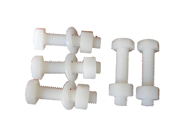
In the field of high-end engineering plastics, MC nylon (monomer casting nylon) has become an ideal material for functional parts such as bearings, gears, and structural bushings due to its excellent wear resistance, high mechanical strength, and low friction coefficient. However, its excellent toughness also brings processing challenges – traditional cutting is prone to causing material springback, burr growth, and thermal deformation.
Modern CNC technology, through precise parameter control and intelligent process design, is pushing the customized production of MC nylon special-shaped parts to new heights of precision and efficiency.
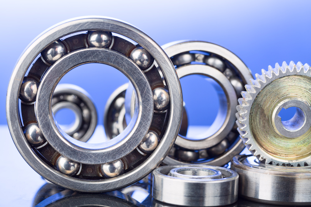
MC Nylon Bearings and Gears – Precision Engineering Components
MC Nylon Material Properties & Technical Specifications
Key Material Characteristics
| Density | 1.14-1.15 g/cm³ |
| Tensile Strength | 75-85 MPa (GB/T 1040) |
| Flexural Modulus | 3500-4100 MPa (ISO 527) |
| Compressive Strength | 26/51 MPa (1%/2% strain, ISO 604) |
| Heat Resistance | Continuous use up to 130°C |
| Water Absorption | 0.3-1% (24h immersion) |
| Dielectric Constant | 3.9 (ASTM D150) |
* Test data for reference only, actual values may vary by batch
Testing & Quality Assurance
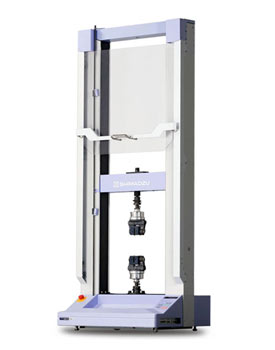
Universal Testing Machine for Material Property Verification
Testing Standards Compliance
- ISO 527 – Tensile Properties of Plastics
- ISO 604 – Compressive Properties of Plastics
- ASTM D150 – AC Loss Characteristics and Permittivity
- GB/T 1040 – Plastic Tensile Testing Method
- DIN EN ISO 527 – International Standard Compliance
Quality Certifications & Industry Standards
FDA Food Grade
Compliant with FDA 21 CFR 177.1500 for food contact
RoHS Certified
EU Directive 2011/65/EU, hazardous substance free
ISO 9001:2015
Quality management system certification
Industry Standards Compliance
Mechanical Testing
- ISO 527 – Tensile testing
- ISO 604 – Compressive testing
- ISO 178 – Flexural testing
- ISO 62 – Izod impact testing
Environmental Testing
- ISO 62 – Water absorption
- ISO 11357 – Thermal analysis
- UL 94 – Flammability testing
- ASTM D570 – Moisture absorption
Electrical Testing
- ASTM D150 – Dielectric constant
- ASTM D257 – Volume resistivity
- ASTM D495 – Arc resistance
- IEC 60112 – Tracking index
2026 CNC Machining Trends for MC Nylon
Sustainable Bio-based MC Nylon
- 30-40% carbon reduction compared to traditional MC nylon
- Recyclable materials with enhanced environmental performance
- Maintains same mechanical properties as standard MC nylon
AI-Enhanced Parameter Optimization
- Real-time cutting parameter adjustment
- 50% reduction in burr formation
- 35% increase in tool life through predictive maintenance
Medical & Food Industry Growth
- 45% increased demand for medical-grade MC nylon
- New regulations compliance for plastic food contact
- Enhanced biocompatibility requirements
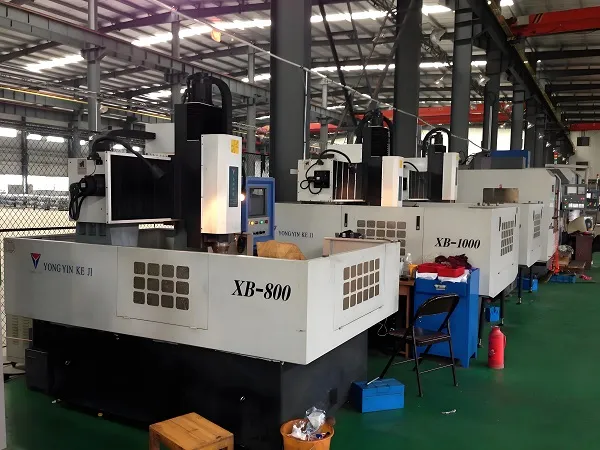
CNC Machining Process & Technology
Advanced Machining Technology
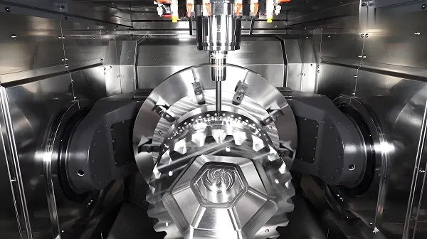
5-Axis Simultaneous Machining
Our 5-axis CNC machining centers enable complex geometry processing with high precision. The simultaneous 5-axis movement allows for:
- Complex curved surface machining with ±0.01mm accuracy
- One-setup processing for multi-face components
- Reduced setup time by 60% compared to traditional methods
- Improved surface finish (Ra ≤ 0.8μm)
High-Speed Machining
High-speed spindle technology (up to 12,000 RPM) with advanced tooling:
- Diamond-coated carbide tools for optimal wear resistance
- High-pressure coolant system (70 bar) for chip evacuation
- Thermal error compensation for dimensional stability
- Processing efficiency improved by 45%
Machining Process Visualization
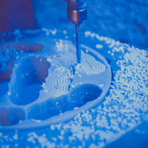
High-Speed CNC Machining of MC Nylon Components
Process Flow
- Material pre-drying (80°C, 4 hours)
- CNC rough machining with 0.5mm allowance
- Intermediate stress relief (60°C, 2 hours)
- CNC finish machining to final dimensions
- On-machine precision inspection
- Surface treatment and deburring
- Final quality control and packaging
I. Material Characteristics and Processing Challenges
The mechanical properties of MC nylon (such as Type 6/Type 12) are significantly different from those of metals, requiring specialized CNC machining solutions.
Key Material Properties
- High toughness and low thermal conductivity: Tensile strength reaches 90 MPa, but thermal conductivity is only 0.3 W/m·K. Cutting heat accumulates easily, leading to softening and deformation.
- Hygroscopic sensitivity: When moisture content of undried material is > 0.8%, shrinkage rate after processing fluctuates between 0.3% – 0.8%, affecting dimensional stability.
- Tendency to stick to the tool: Easy to adhere to the tool during cutting, especially when processing deep grooves or thin-walled structures, leaving burrs on the surface.
Key Countermeasures
Pre-drying treatment (80°C/4 hours, controlling humidity to < 0.2% moisture content) + constant-temperature cooling system (air-cooling or mist-cooling, avoiding water-based coolant penetration).
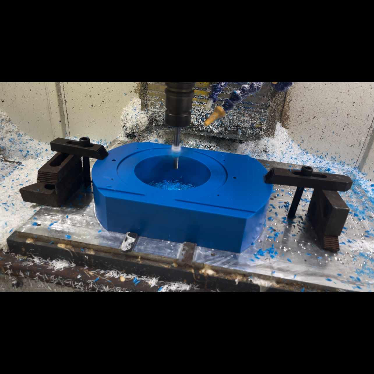
CNC Machining of Blue MC Nylon Components
II. Core of Process Optimization
(1) Tool Selection and Geometric Design
- Priority on sharp edge: Use diamond-coated carbide end-mills with a rake angle γ = 15°-20° to reduce cutting resistance; tool-tip arc radius is R0.2-R0.5 to suppress edge chipping.
- Dedicated chip-evacuation grooves: Increase the chip-holding groove volume by 30% and set the helix angle at 35°-45° to improve the long-chip evacuation efficiency.
(2) Scientific Matching of Cutting Parameters
In view of the viscoelastic response characteristics of MC nylon, it is necessary to balance the cutting force and heat accumulation:
| Process Type | Spindle Speed (RPM) | Feed Rate (mm/rev) | Cutting Depth (mm) | Linear Speed (m/min) |
|---|---|---|---|---|
| Roughing | 2500-3500 | 0.15-0.25 | ≤D* | 120-150 |
| Finishing | 4000-6000 | 0.02-0.08 | 0.1-0.3 | 180-220 |
*D is the tool diameter. Avoid full-edge cutting (recommended radial cutting width ≤ 0.6D)
(3) Multi-axis Dynamic Compensation Technology
- 5-axis simultaneous trochoidal milling: For deep-cavity special-shaped parts (such as turbine blade dovetail grooves), adopt a contact angle control strategy (Contact Angle ≤ 45°). The tool path automatically integrates spiral penetration and trochoidal expansion, reducing the cutting force by 40%.
- Real-time vibration suppression: Equipped with high-end CNC systems such as FAGOR 8055, with a pre-processing time ≤ 1.4ms. Enable G51 dynamic smoothing at the inflection points of the surface to avoid vibration marks.
III. High-speed Finishing and Surface Quality Control
(1) Stratified Polishing Strategy
- Gradient control of finishing allowance: Leave a roughing allowance of 0.5mm → semi-finishing allowance of 0.15mm → final milling in two passes (first pass 0.1mm, last pass 0.05mm) to eliminate springback errors.
- Constant surface linear speed cutting: Enable the CSS mode in the finishing stage to ensure the consistency of Ra in the curvature-changing area (measured Ra ≤ 0.8μm).
(2) Deburring and Dimensional Stabilization
- On-machine micro-chamfering process: Immediately after finishing milling, use a 0.2mm ball-nose end-mill to lightly repair the edges at 8000 RPM and 0.01mm/rev.
- Post-treatment aging: After processing, store at a constant temperature (60°C) for 24 hours to release internal stress, and the dimensional tolerance is stabilized within ±0.03mm.
Quality Testing & Inspection Procedures
Dimensional Inspection
Coordinate Measuring Machine (CMM)
- Measurement accuracy: ±0.002mm
- Multi-point scanning for complex surfaces
- 3D model comparison and deviation analysis
- Full inspection report with tolerance analysis
On-Machine Probing
- Renishaw RMP600 probe system
- Real-time dimension verification during processing
- Automatic tool offset compensation
- Reduced inspection time by 70%
Material Performance Testing
Mechanical Property Testing
- Tensile strength testing per ISO 527
- Impact strength testing per ISO 179
- Hardness testing (Shore D)
- Wear resistance testing (pin-on-disc method)
Environmental Testing
- Heat deflection temperature (HDT) testing
- Chemical resistance testing
- UV resistance testing
- Long-term aging testing (1000 hours)
Quality Control Data
Process Capability (2025 Data)
| Cpk Value | 1.67 (minimum) |
| Yield Rate | 98.5% |
| On-time Delivery | 99.2% |
| Customer Satisfaction | 96.8% |
* Data for reference only, subject to actual production conditions
IV. Typical Application Cases (2025-2026)
Lightweight Gearbox Planet Carrier
Challenge: Asymmetric arms with complex contours and bearing holes requiring high positional accuracy.
Solution: 5-axis simultaneous machining center, completed contour milling and boring in one clamping (hole position accuracy ±0.015mm). Weight reduction of 35% compared to metal alternatives.
Ultra-low Friction Bearing Bush
Challenge: Internal spiral oil grooves with precise dimensions (width 1.2mm ± 0.05, depth-to-diameter ratio 1:8).
Solution: Turning-milling composite center integrated precision turning + engraving of internal spiral oil grooves. Friction coefficient reduced by 40% compared to standard bushings.
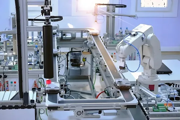
Bionic Robot Joint Parts
Challenge: Complex curved surfaces requiring high surface finish and dimensional stability.
Solution: Based on iMachining HPC strategy, large cutting depth (4×D) combined with variable-step-pitch spiral toolpaths. Processing time reduced by 35%.
V. Digital Closed-loop: Integrated Assurance from Design to Quality Inspection
1. CAD/CAM Intelligent Programming
Use the Creo NC – PerfectPart module to automatically generate the probe measurement path based on the 3D model of the workpiece, shortening the alignment time by 50%.
2. On-machine Inspection Integration
The Renishaw RMP600 probe realizes sub-micron-level verification of key dimensions after processing (such as flatness of the mating surface ≤ 0.01mm).
3. Process Parameter Cloud Library
Accumulate an MC nylon material database (including cutting force models, tool wear curves) and iteratively optimize the processing plan for new parts. 2026 AI-driven optimization reduces setup time by 40%.
Frequently Asked Questions (2026 Update)
Q1: How to prevent moisture absorption deformation in MC nylon parts?
A: Pre-drying is essential (80°C for 4 hours to reduce moisture content below 0.2%). After processing, immediate sealing packaging with desiccant is recommended. For 2026, we offer new moisture-stabilized MC nylon grades with 50% reduced hygroscopicity.
Q2: What is the best method for deburring MC nylon parts?
A: On-machine micro-chamfering with 0.2mm ball-nose end-mill at 8000 RPM is most effective. For complex geometries, we use 2026’s new cryogenic deburring technology that removes burrs without affecting surface finish.
Q3: Is MC nylon suitable for food contact applications?
A: Yes, our FDA-compliant MC nylon grades meet FDA 21 CFR 177.1500 regulations. For 2026, we’ve introduced new bio-based MC nylon that not only meets food safety standards but also offers 30% carbon reduction.
Q4: What are the medical application considerations for MC nylon?
A: Medical-grade MC nylon must meet ISO 10993 biocompatibility standards. Our 2026 medical-grade materials offer enhanced sterilization resistance (up to 1000 autoclave cycles) and improved wear resistance for long-term implant applications.
Customize Your Engineering Plastic Solution
When you face the needs of special-shaped structures with high loads and low wear, the integration of MC nylon and CNC precision processing means a breakthrough in the balance of performance and cost. Relying on multi-axis turning-milling centers (standard 12,000 RPM spindle + high-pressure air-cooling) and material process laboratories, we provide a full-link customized service from material pre-treatment → dynamic cutting simulation → finished-product aging control.
Are you facing the following challenges?
- Vibration control in the processing of complex-surface MC nylon parts?
- Rapid process deployment for small-batch and multi-variety orders?
- Long-term stability requirements for micron-level accuracy of assembly interfaces?
“At the boundary of rigidity and flexibility, we use data as a blade to carve the precise soul of engineering plastics.”