When spindle speed increases from 12,000rpm to 18,000rpm, the machining precision of an aerospace component improves by 30% while manufacturing costs decrease by 15%.
In precision manufacturing, micron-level errors can determine product success or failure. A human hair has a diameter of approximately 0.07mm, while modern CNC machining can achieve precision within 0.001mm—equivalent to 1/70th of a hair’s diameter.
1. Fundamental Theory of CNC Machining Precision
1.1 Precision Grade Classification System
CNC machining precision is primarily classified through the International Tolerance Grade (IT Grade) system:
IT Tolerance Grade System:
- IT01-IT5: High precision grade, tolerance range from micrometers to sub-micrometers
- IT6-IT8: Medium precision grade, tolerance range from micrometers to tens of micrometers
- IT9-IT18: Normal grade, tolerance range above one hundred micrometers
Machine Tool Precision Grade Standards (GB/T25372-2010):
- Normal Grade (P): Positioning accuracy ≤0.02mm, repeatability ≤0.015mm
- Precision Grade (M): Positioning accuracy ≤0.012mm, repeatability ≤0.008mm
- High Precision Grade (G): Positioning accuracy ≤0.004mm, repeatability ≤0.003mm
1.2 Surface Quality Control Indicators
Surface roughness is an important indicator for measuring machining quality:
|
Machining Grade
|
Ra Value Range
|
Surface Characteristics
|
Typical Applications
|
|
Rough Machining
|
12.5-20μm
|
Obvious tool marks
|
Structural parts
|
|
Semi-finishing
|
3.2-6.3μm
|
Visible tool marks
|
General components
|
|
Finishing
|
0.8-1.6μm
|
Slight tool marks
|
Fitting parts
|
|
Precision Machining
|
0.2-0.4μm
|
Mirror finish
|
Precision components
|

2. Analysis of Factors Affecting CNC Machining Precision
2.1 Machine Tool Factors
Spindle System Precision:
- Spindle radial runout: Every 0.001mm increase causes 0.003mm machining error
- Spindle axial runout: Directly affects end face machining precision
- Spindle speed stability: ±5% speed fluctuation increases surface roughness by 30%
Feed System Precision:
- Ball screw precision grade: C3 grade screw positioning error ≤0.008mm/300mm
- Guideway precision: Straightness error of 0.01mm per meter causes workpiece parallelism error
- Servo system response: Response speed directly affects contour machining precision
2.2 Tool Factors
Tool Material Selection:
- High-speed steel tools: Suitable for low-speed machining, precision life approximately 8 hours
- Carbide tools: Suitable for high-speed machining, precision life up to 40 hours
- Cubic boron nitride tools: Suitable for super-hard materials, precision up to IT5 grade
Tool Geometry Parameters:
- Rake angle selection: 15-20° for aluminum alloys, 5-10° for steel parts
- Clearance angle selection: 8-12° for finishing, 5-8° for roughing
- Tool nose angle: Affects chip flow direction and cutting force distribution
Tool Wear Control:
- Tool wear of 0.01mm increases part dimension error by 0.015mm
- Flank wear VB value controlled within 0.1-0.3mm range
- Implement tool life management system

2.3 Process Parameter Settings
Cutting Parameter Optimization:
|
Material
|
Tool Material
|
Cutting Speed (m/min)
|
Feed Rate (mm/r)
|
Depth of Cut (mm)
|
|
Aluminum Alloy
|
Carbide
|
300-600
|
0.1-0.3
|
1-5
|
|
Carbon Steel
|
Carbide
|
100-300
|
0.1-0.25
|
1-4
|
|
Stainless Steel
|
Carbide
|
50-150
|
0.05-0.2
|
0.5-2
|
|
Titanium Alloy
|
Carbide
|
30-100
|
0.05-0.15
|
0.3-1.5
|
Machining Path Planning:
- Adopt climb milling to reduce tool wear
- Use layer cutting for roughing, contour machining for finishing
- Reasonably arrange cutting sequence to avoid workpiece deformation
2.4 Environmental Factor Control
Temperature Control Requirements:
- Precision machining workshop temperature: 20±1℃
- Temperature change rate: No more than 0.5℃ per hour
- Relative humidity: 45-65%
Vibration Control Measures:
- Machine tool installed with anti-vibration pads, vibration amplitude controlled within 0.002mm
- Keep away from vibration sources such as stamping and forging equipment
- Adopt vibration isolation foundation design
3. CNC Machining Precision Control Technology
3.1 Error Compensation Technology
Geometric Error Compensation:
- Use laser interferometer to measure machine geometric errors
- Perform error compensation through CNC system parameters
- Can improve precision by 20-40%
Thermal Error Compensation:
- Install temperature sensors on machine tools
- Establish thermal error prediction model
- Real-time compensation of thermal deformation errors
Tool Compensation Technology:
- Tool length compensation: Compensate for tool wear and replacement errors
- Tool radius compensation: Ensure contour machining precision
- Tool wear compensation: Automatically compensate wear based on machining time
3.2 High-Precision Machining Processes
High-Speed Machining Technology:
- Spindle speed: 8000-40000rpm
- Feed rate: 20-60m/min
- Surface roughness can reach Ra 0.4-0.8μm
Ultra-Precision Cutting Technology:
- Cutting speed: 1000-5000m/min
- Feed rate: 0.001-0.01mm/r
- Machining precision can reach above IT5 grade
Electrical Discharge Machining Technology:
- Machining precision: ±0.002mm
- Surface roughness: Ra 0.1-0.8μm
- Suitable for complex shapes and hard materials
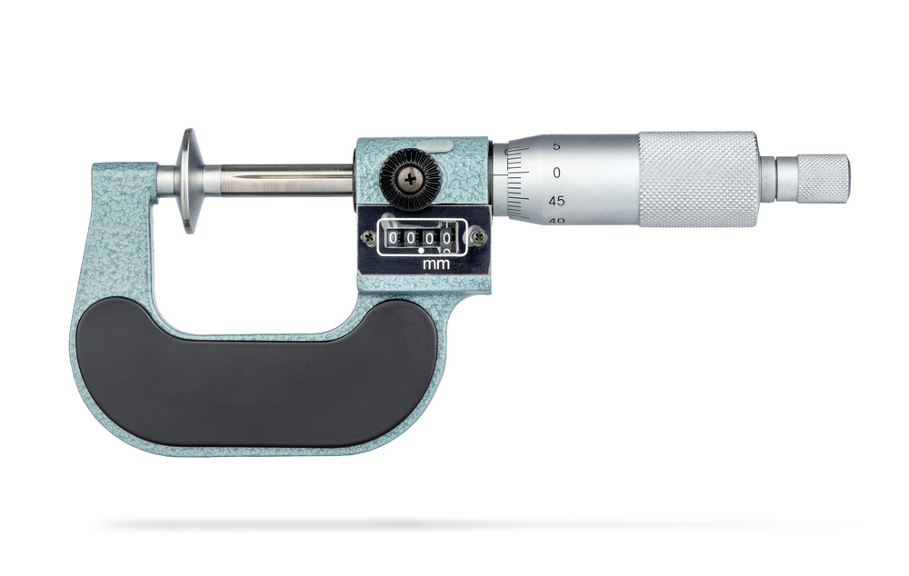
3.3 Quality Inspection Technology
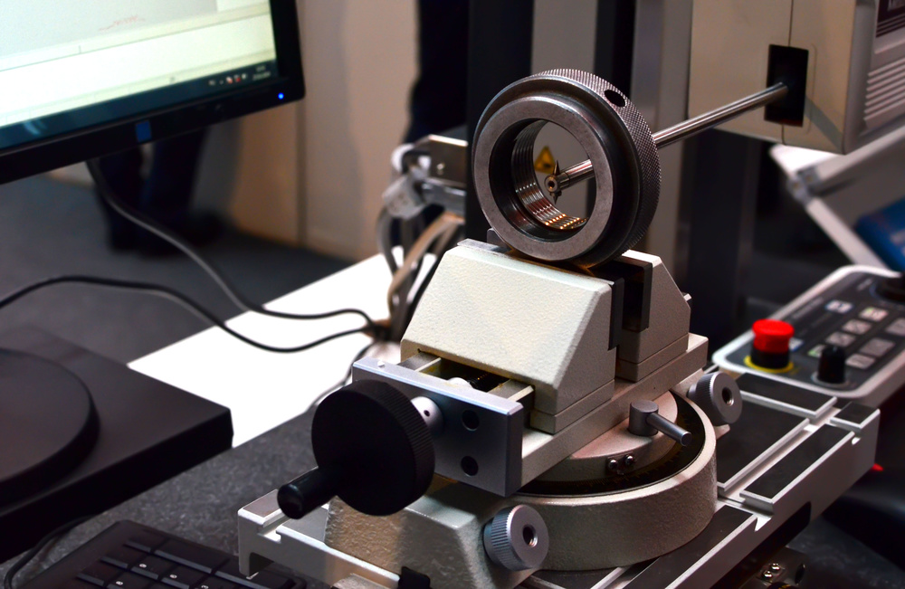
On-Machine Inspection Systems:
- Laser measuring instrument: Precision ±0.001mm
- Probe measuring system: Repeatability ±0.0005mm
- Real-time monitoring of machining process
Offline Inspection Equipment:
- Coordinate measuring machine: Measurement accuracy ±0.001mm
- Roundness tester: Measurement accuracy ±0.0001mm
- Surface roughness tester: Measurement range 0.001-16μm
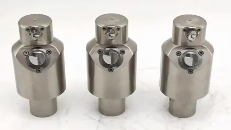
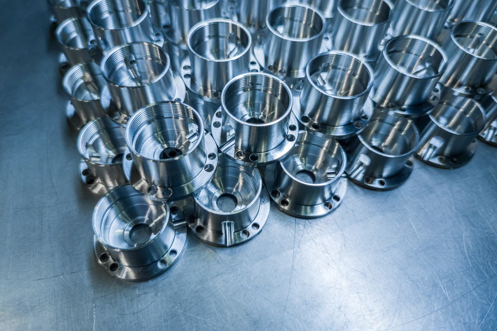
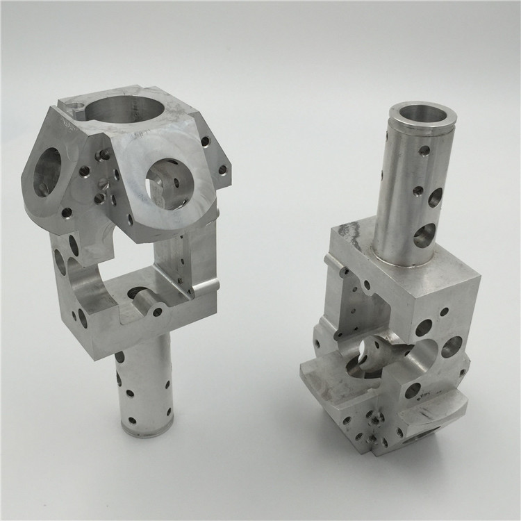
4. Practical Application Case Analysis
4.1 Aerospace Component Machining Case
Part Name: Aerospace engine turbine blade
Material: Titanium alloy TC4
Precision Requirements: ±0.005mm, Ra 0.2μm
Machining Plan:
- Use 5-axis machining center
- Spindle speed: 18000rpm, feed rate: 30m/min
- Tool: Ultra-fine grain carbide with TiAlN coating
- Cutting parameters: V=80m/min, f=0.1mm/r, ap=0.5mm
Quality Control Measures:
- Machining in temperature-controlled workshop, temperature controlled at 20±0.5℃
- Use on-machine laser measuring system
- Conduct sampling inspection every 10 pieces
Machining Results:
- Dimensional accuracy: ±0.003mm
- Surface roughness: Ra 0.15μm
- Qualification rate: 98.5%
4.2 Precision Mold Machining Case
Part Name: Mobile phone housing injection mold
Material: Die steel H13
Precision Requirements: ±0.01mm, Ra 0.4μm
Machining Process Flow:
- Rough machining: High-speed milling to remove most stock
- Semi-finishing: Ball end mill, leaving 0.3mm stock
- Heat treatment: Quenching and tempering to HRC48-52
- Finishing: High-speed milling to meet dimensional requirements
- Polishing: Manual polishing to Ra 0.4μm
Key Technical Points:
- Use high-speed machining center with 15000rpm spindle
- Use solid carbide ball end mills
- Adopt climb milling to reduce tool wear
- Optimize machining path to avoid overcutting
4.3 Medical Device Machining Case
Part Name: Artificial joint
Material: Medical stainless steel 316L
Precision Requirements: ±0.008mm, Ra 0.3μm
Machining Characteristics:
- Complex surface machining requiring 5-axis linkage
- High surface quality requirements, needing mirror finish
- Biocompatibility requirements, no burrs or defects
Machining Process:
- Forging blank pretreatment
- CNC turning to machine datum surfaces
- 5-axis milling to machine complex surfaces
- Grinding to improve precision
- Polishing to meet surface requirements
5. CNC Machining Precision Improvement Practical Guide
5.1 Equipment Selection Recommendations
Normal Precision Requirements (IT8-IT10):
- Economic CNC machining center
- Spindle speed: 6000-8000rpm
- Positioning accuracy: ±0.015mm
Medium Precision Requirements (IT7-IT8):
- Standard CNC machining center
- Spindle speed: 8000-12000rpm
- Positioning accuracy: ±0.008mm
High Precision Requirements (IT5-IT7):
- High-precision CNC machining center
- Spindle speed: 12000-24000rpm
- Positioning accuracy: ±0.003mm
5.2 Tool Selection Strategy
Tool Selection by Material:
- Aluminum alloys: High-speed steel, carbide, diamond tools
- Steel parts: Carbide, coated tools
- Stainless steel: Ultra-fine grain carbide, CBN tools
- Titanium alloys: Ultra-fine grain carbide, cermet tools
Selection by Machining Stage:
- Roughing: Inserted tools, high-speed steel tools
- Semi-finishing: Solid carbide tools
- Finishing: Coated tools, ultra-fine grain tools

5.3 Process Optimization Methods
Cutting Parameter Optimization Steps:
- Determine initial parameters based on material and tool
- Conduct trial cutting tests and record machining results
- Analyze surface quality and dimensional accuracy
- Adjust parameters and repeat tests
- Determine optimal parameter combination
Machining Path Optimization Principles:
- Reduce empty travel time to improve efficiency
- Reasonably arrange cutting sequence to avoid workpiece deformation
- Adopt shortest path principle
- Consider tool life and machining quality
5.4 Quality Control System
Inspection Plan Development:
- First article inspection: Comprehensive inspection of all dimensions
- Process inspection: 10-20% sampling by batch
- Last article inspection: Comparison with first article to confirm stability
Statistical Process Control:
- Establish control charts to monitor dimensional change trends
- Calculate process capability indices Cp, Cpk
- Take immediate corrective actions when Cpk<1.33
Equipment Maintenance:
- Daily inspection: Lubricant level, air pressure, coolant
- Weekly inspection: Tool wear, fixture precision
- Monthly inspection: Machine precision, lubrication system
- Annual inspection: Comprehensive precision calibration, component replacement
6. Common Precision Problem Solutions
6.1 Dimensional Precision Deviation
Root Cause Analysis:
- Severe tool wear
– Unreasonable cutting parameters
- Machine precision degradation
- Temperature change effects
Solutions:
- Timely tool replacement, establish tool life management
- Optimize cutting parameters to reduce cutting forces
- Regular machine precision calibration
- Improve workshop environmental temperature control
6.2 Surface Roughness Exceeding Standards
Common Causes:
– unreasonable tool geometry parameters
- Low cutting speed
- Excessive feed rate
- Insufficient coolant
Improvement Methods:
- Select appropriate tool rake and clearance angles
- Increase cutting speed, adopt high-speed machining
- Reduce feed rate, increase number of passes
- Optimize coolant type and supply method
6.3 Geometric Tolerance Deviation
Typical Problems:
- Flatness deviation
- Cylindricity deviation
- Concentricity deviation
- Parallelism deviation
Solution Strategies:
- Check machine geometric accuracy and perform error compensation
- Optimize fixture design to improve clamping rigidity
- Reasonably arrange machining sequence to reduce deformation
- Adopt step-by-step machining to control cumulative errors
6.4 Balancing Machining Efficiency and Precision
Optimization Strategies:
– Pursue Efficiency for roughing, ensure precision for finishing
- Adopt high-speed machining technology to balance efficiency and quality
- Reasonably arrange processes to reduce clamping times
- Utilize automation technology to improve consistency
Cost-Benefit Analysis:
- IT5 grade precision costs 3-5 times that of IT8 grade
- Every precision grade improvement increases costs by approximately 40%
– Select the accuracy grade reasonably based on functional requirements

By systematically mastering CNC machining precision control technology and combining practical production experience, machining quality can be effectively improved, production costs reduced, and enterprise competitiveness enhanced. In the field of precision manufacturing, precision control is the core technology that requires continuous improvement and refinement.
Disclaimer
- All information, opinions, and data contained in this article are for the purpose of information transmission only and do not constitute any advice on investment, transactions, law, medical care, or other matters.
- The content of the article is compiled based on public information or created based on the author’s personal understanding. Although every effort is made to ensure accuracy, it does not guarantee the completeness, accuracy, and timeliness of the information, nor does it bear any responsibility for any losses caused by the use of the content of this article.
- If the article involves third-party opinions, pictures, data, and other content, the copyright belongs to the original author. In case of infringement, please contact us for deletion.
- Readers should make independent decisions based on their actual situation and combined with professional opinions. The user shall bear all consequences arising from the use of the content of this article.