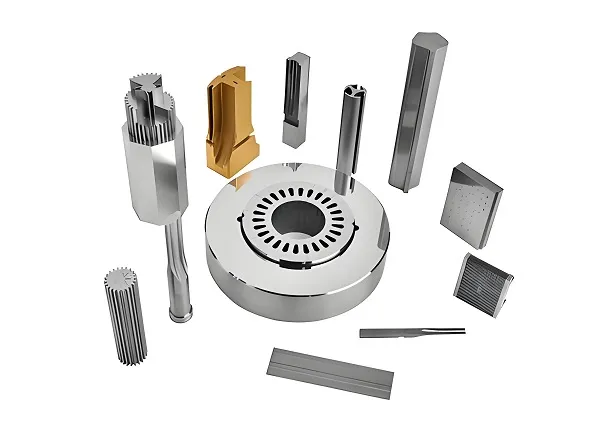
- Basic milling processes include:
- Face milling
- Slot milling
- Side milling
- Profile milling
- Advanced milling processes include:
- Ramp milling
- Thread interpolation
- Trochoidal milling
- Push – pull profile milling
- Plunge milling
- Contour milling
- Drilling
- Operators should wear tight – fitting work clothes with cuffs tightly tied, wear a safety cap, wear safety goggles during high – speed milling, wear a mask when milling cast iron parts. During operation, wearing gloves is strictly prohibited to prevent the hand from being caught between the rotating tool and the workpiece.
- Before operation, check whether all components of the milling machine and safety devices are safe and reliable, and check whether the electrical part of the equipment is in good safety and reliability condition.
- When loading and unloading workpieces, the worktable should be retracted to a safe position. When using a wrench to tighten the workpiece, the direction of force should avoid the milling cutter to prevent hitting the tool or fixture when the wrench slips.
- When installing and removing the milling cutter, use a special gasket for padding, and do not hold the milling cutter directly by hand.
- When milling irregular workpieces and using a vise, dividing head, or special fixture to hold the workpiece, the center of gravity of the irregular workpiece and the vise, dividing head, special fixture, etc. should be placed as much as possible in the middle part of the worktable to avoid uneven stress on the worktable and deformation.
- During fast or automatic feed milling, do not move the worktable to the two extremes to prevent squeezing the screw rod.
- When the machine tool is running, do not adjust, measure the workpiece, or change the lubrication method to prevent fingers from being injured by touching the tool.
- Do not brake the milling cutter by hand before it completely stops rotating.
- Do not clear the chips by hand during milling, nor blow them with the mouth to prevent the chips from damaging the skin and eyes.
- When the machine is in rapid feed, open the handwheel clutch to prevent the handwheel from rotating rapidly and hurting people.
- When the worktable changes direction, first stop the reversing handle in the middle position, and then change the direction. Do not change the direction directly.
- When milling keyway shafts or cutting thin workpieces, be careful not to damage the dividing head or the worktable surface.
- When milling a plane, a cutter head with more than four cutting edges must be used, and appropriate cutting parameters should be selected to prevent the machine tool from vibrating during milling.
- After work, stop the worktable in the middle position and lower the knee to the lowest position.
- For CNC vertical milling machines, before work, pre – select relevant work procedures, spindle speed, tool feed rate, tool movement trajectory, and continuous over – travel according to the process requirements. Place the electrical knob in the “adjustment” position for test – running. After confirming no problems, place the electrical knob in the automatic or semi – automatic position for work.
When milling with a cylindrical milling cutter, the milling methods can be divided into up milling and down milling. When the feed direction of the workpiece is the same as the cutting speed direction of the cylindrical milling cutter, it is called down milling. When the feed direction of the workpiece is opposite to the cutting direction of the cylindrical milling cutter, it is called up milling.
Down milling is beneficial for improving the tool life and the stability of workpiece clamping, but it is likely to cause the worktable to move jerkily and even cause accidents. Therefore, when down milling, the machine tool should be equipped with a device to eliminate the clearance between the screw rod and the nut, and the processing range of down milling is suitable for workpieces without hard skins. During finish – machining, the milling force is small, and it is not easy to cause the worktable to move jerkily, so down milling is mostly used. During down milling, there is always a downward component force pressing the workpiece, making the milling stable. The cutting thickness of each tooth decreases from the maximum to zero, which is easy to cut into the workpiece, and the extrusion and friction on the machined surface when cutting out are also small, resulting in a higher surface quality of the machined surface and less power consumption in the feed direction.
Up milling is mostly used for rough – machining. When machining castings and forgings with hard skins, up milling is adopted. When using a milling machine without a screw – nut adjustment mechanism for machining, up milling should also be used. During up milling, since the cutting edge does not cut into the workpiece surface from the beginning, when milling a workpiece with a hard skin on the surface, the damage to the cutting edge is minimized. However, at this time, the cutting thickness of each tooth increases from zero to the maximum. Due to the arc of the cutting edge, the tooth has to slide a certain distance before it can cut into the workpiece. The cutting edge is prone to wear, and the machined surface is squeezed and rubbed, affecting the surface quality of the machined surface.
- Check the power and stiffness of the machine tool to ensure that the diameter of the milling cutter used can be used on the machine tool with the shortest possible tool overhang.
- The number of teeth of the milling cutter should be appropriate to ensure that not too many inserts engage with the workpiece simultaneously during machining to avoid vibration. There should be enough inserts engaging with the workpiece when milling narrow workpieces or cavities.
- Appropriate feed per tooth to obtain good cutting results when the chip is thick enough, thus reducing tool wear. Use positive – rake – angle insert grooves to obtain smooth cutting results and the lowest power consumption.
- The diameter of the milling cutter suitable for the width of the workpiece.
- Correct principal cutting edge angle (45 degrees is suitable for general milling).
- Appropriate position of the milling cutter.
- Use cutting fluid only when necessary. Dry milling usually results in a better tool life.