Introduction
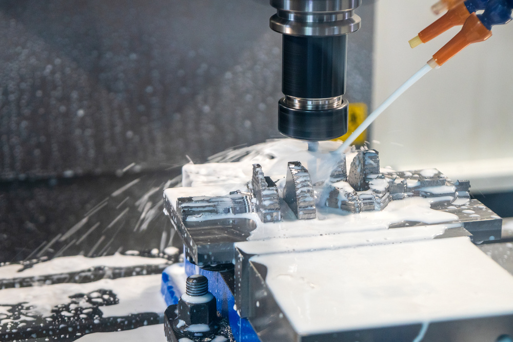
CNC (Computer Numerical Control) machining is a sophisticated manufacturing process that transforms raw materials into precise components using computer-controlled machine tools. This technology has revolutionized modern manufacturing, offering unparalleled precision, consistency, and efficiency across various industries including aerospace, automotive, medical, and electronics.
Understanding the complete CNC machining process flow is essential for engineers, manufacturers, and procurement professionals who want to optimize production, ensure quality, and reduce costs. This comprehensive guide will walk you through every stage of the CNC machining workflow, from initial design to final delivery.
1. Design and Requirements Analysis
1.1 Product Design and Specification
The CNC machining process begins with a thorough understanding of the part requirements and detailed product design.
Key Activities:
- Requirements Gathering: Collect detailed specifications including dimensions, tolerances, material requirements, surface finish, and functional needs
- Feasibility Study: Evaluate design manufacturability (DFM – Design for Manufacturability)
- Material Selection: Choose appropriate materials based on functional requirements, cost, and machinability
- Cost Estimation: Provide preliminary cost analysis based on complexity and production volume
Design Considerations:
- Tolerance Analysis: Define appropriate tolerances based on functional requirements
- Surface Finish Requirements: Specify surface roughness (Ra values) for different surfaces
- Material Compatibility: Ensure material properties match application needs
- Production Volume: Consider batch size for process optimization
1.2 CAD Modeling and Engineering Design
CAD (Computer-Aided Design) is the foundation of the CNC machining process:
CAD Software Options:
- SolidWorks: Widely used for mechanical design
- AutoCAD: Popular for 2D drafting and 3D modeling
- Fusion 360: Cloud-based solution with integrated CAM capabilities
- CATIA: Advanced software for complex aerospace and automotive designs
- NX (Unigraphics): Comprehensive solution for product development
Modeling Best Practices:
- Create parametric models for easy modification
- Define clear reference planes and coordinate systems
- Include all necessary dimensions and tolerances
- Verify design integrity and manufacturability
- Export models in standard formats (STEP, IGES, STL)
2. CAM Programming and Toolpath Generation
2.1 CAM Software and Toolpath Planning
CAM (Computer-Aided Manufacturing) software converts CAD models into machine-readable code that controls the CNC machine.
CAM Software Solutions:
- Mastercam: Industry-standard CAM software
- GibbsCAM: User-friendly interface with powerful capabilities
- EdgeCAM: Integrated CAD/CAM solution
- HyperMill: Specialized for complex 5-axis machining
- BobCAD-CAM: Cost-effective solution for small to medium shops
Toolpath Generation Process:
- Import CAD Model: Load the 3D model into the CAM software
- Define Workpiece Setup: Establish stock size, orientation, and fixture locations
- Select Machining Operations: Choose appropriate operations (roughing, finishing, drilling)
- Tool Selection: Pick suitable cutting tools based on material and geometry
- Cutting Parameters: Set spindle speed, feed rate, and depth of cut
- Toolpath Calculation: Generate the optimal toolpath for each operation
- Simulation: Verify toolpath for collisions and errors
2.2 Cutting Parameters and Optimization
Key Cutting Parameters:
|
Parameter
|
Description
|
Typical Values
|
|
Spindle Speed
|
Rotational speed of the cutting tool
|
1,000-20,000 RPM
|
|
Feed Rate
|
Speed at which the tool moves through material
|
50-5,000 mm/min
|
|
Depth of Cut
|
Amount of material removed per pass
|
0.1-5 mm
|
|
Cutting Width
|
Width of cut for milling operations
|
10-100% of tool diameter
|
Optimization Strategies:
- High-Speed Machining (HSM): Use higher spindle speeds and feed rates with smaller depths of cut
- Adaptive Clearing: Optimize toolpaths to maintain constant cutting load
- Trochoidal Milling: Reduce cutting forces with circular tool movements
- Tool Life Management: Balance speed and feed to maximize tool performance
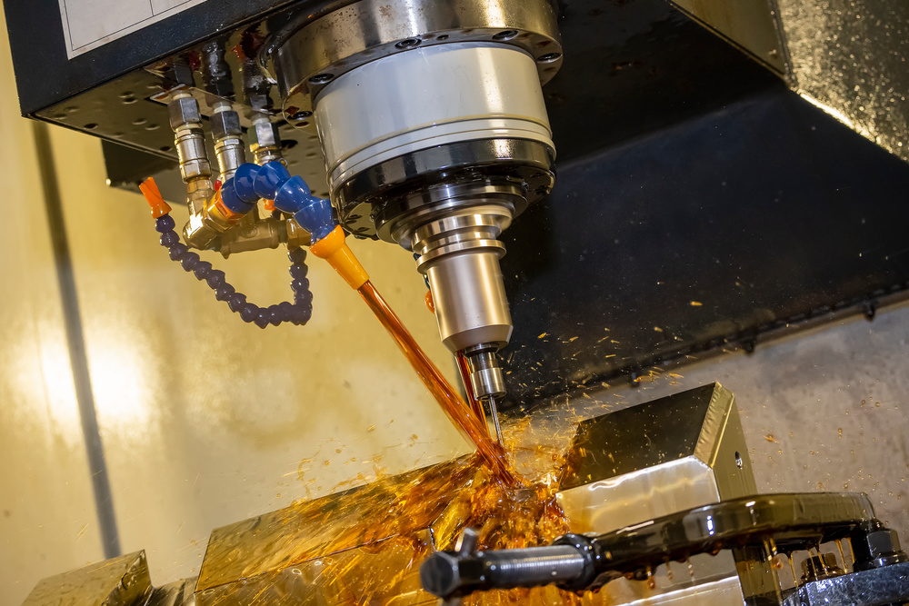
- Coolant Strategy: Select appropriate cooling method based on material and operation
2.3 G-Code and Machine Control
The final output of the CAM process is G-code, the standard programming language for CNC machines.
G-Code Basics:
- G-Codes: Control machine movements (G00: rapid move, G01: linear feed, G02/G03: circular feed)
- M-Codes: Control machine functions (M03: spindle forward, M08: coolant on, M30: program end)
- Feed Rates: F-values for linear feed rates
- Spindle Speeds: S-values for spindle RPM
- Tool Changes: T-codes for tool selection, M06 for tool change
Machine-Specific Considerations:
- Post-Processors: Convert CAM output to machine-specific G-code
- Control Systems: Fanuc, Siemens, Haas, Mitsubishi, Heidenhain
- Machine Limits: Work envelope, spindle capabilities, tool changer capacity
- Safety Features: Implement proper safety codes and interlocks
3. Material Preparation and Setup
3.1 Material Selection and Preparation
Proper material preparation is critical for successful CNC machining.
Common Materials:
Metals:
- Aluminum Alloys: 6061-T6 (general purpose), 7075-T6 (high strength), 5052 (good corrosion resistance)
- Steel Alloys: 1018 (mild steel), 4140 (alloy steel), 304/316 (stainless steel)
- Specialty Metals: Titanium Ti-6Al-4V, Inconel 718, Brass, Copper
- Tool Steels: H13, S7, D2 for high-wear applications
Non-Metals:
- Plastics: Acetal (Delrin), PEEK, Nylon, PTFE (Teflon), ABS, PVC
- Composites: Carbon Fiber, Fiberglass, G10/FR4
- Wood and Foam: For prototypes and models
Material Preparation Steps:
- Stock Sizing: Cut raw material to appropriate dimensions
- Surface Preparation: Remove any oxidation, rust, or contaminants
- Heat Treatment: Perform necessary annealing or stress relieving
- Material Certification: Verify material properties and certifications
- Storage and Handling: Ensure proper storage to prevent damage
3.2 Workholding and Fixturing
Secure and accurate workholding is essential for maintaining precision during machining.
Workholding Methods:
Mechanical Clamping:
- Vises: Standard machine vises, precision vises, angle vises
- Clamps: C-clamps, bar clamps, strap clamps
- Chucks: 3-jaw chucks, 4-jaw chucks, collet chucks
- Fixtures: Custom fixtures for repeatable positioning
Specialized Workholding:
- Vacuum Tables: For flat, thin workpieces
- Magnetic Chucks: For ferrous materials
- Collet Systems: For round workpieces in lathes
- Indexers and Rotary Tables: For multi-sided machining
Fixturing Best Practices:
- Rigidity: Ensure workpiece is securely clamped to minimize vibration
- Accessibility: Position workpiece to allow tool access to all features
- Repeatability: Use locating pins and reference surfaces for consistent positioning
- Minimal Distortion: Avoid over-clamping thin or delicate parts
- Safety: Ensure clamping forces are sufficient for cutting conditions
3.3 Tool Selection and Setup
Proper tool selection and setup directly impact machining quality and efficiency.
Tool Types and Applications:
Milling Tools:
- End Mills: Square end, ball end, corner radius, roughing
- Face Mills: For large flat surfaces
- Drills: Twist drills, spot drills, center drills
- Taps and Thread Mills: For internal threads
- Reamers: For precise hole sizing
- Boring Bars: For large diameter holes
Turning Tools:
- External Turning Tools: For OD turning, facing, profiling
- Internal Turning Tools: For ID turning and boring
- Threading Tools: For external and internal threads
- Grooving Tools: For grooves and recesses
- Parting Tools: For separating finished parts
Tool Material Selection:
- High-Speed Steel (HSS): General purpose, lower cost
- Carbide: Higher speed capabilities, better wear resistance
- Cermet: Improved performance in steel machining
- Ceramic: High-temperature applications
- CBN (Cubic Boron Nitride): For hard materials
- Diamond: For non-ferrous materials and finishing
Tool Setup Process:
- Tool Installation: Mount tools in holders with proper runout control
- Tool Length Offset: Measure tool length and set offsets
- Tool Diameter Compensation: Set tool radius compensation values
- Tool Balancing: Balance tools for high-speed machining
- Cutting Edge Inspection: Check for damage or wear
- Coolant Setup: Position coolant nozzles for optimal cooling
4. CNC Machining Execution
4.1 Machine Setup and Calibration
Proper machine setup ensures accurate and efficient machining.
Machine Preparation Steps:
- Machine Warm-Up: Run spindle and axes at low speeds to stabilize temperature
- Leveling and Alignment: Verify machine level and axis alignment
- Lubrication Check: Ensure proper lubrication of all moving parts
- Coolant System: Check coolant level, concentration, and temperature
- Control System Check: Verify all systems are functioning properly
- Safety Checks: Ensure all safety guards and interlocks are in place
Work Offset Setup:
- Work Offset Setting: Establish workpiece coordinate system (G54-G59)
- Touch Probe Setup: Use touch probes for automated offset measurement
- Edge Finding: Manually set offsets using edge finders
- Tool Length Setting: Measure and set tool length offsets
- Fixture Offset: Set offsets for multiple workpieces
4.2 Trial Run and Program Verification
Before full production, a trial run is essential to verify program correctness.
Verification Process:
- Dry Run: Run program without cutting material to check toolpaths
- Simulation: Use machine simulation to verify program integrity
- Test Cut: Make a test cut in scrap material to verify dimensions
- First Article Inspection: Inspect first part thoroughly before production
- Process Optimization: Adjust parameters based on test results
Common Verification Checks:
- Toolpath Accuracy: Verify tool movements match design intent
- Collision Detection: Check for potential collisions between tool, workpiece, and fixture
- Dimensional Accuracy: Verify critical dimensions match specifications
- Surface Finish: Check surface quality and adjust parameters if needed
- Cycle Time: Evaluate production efficiency and make adjustments
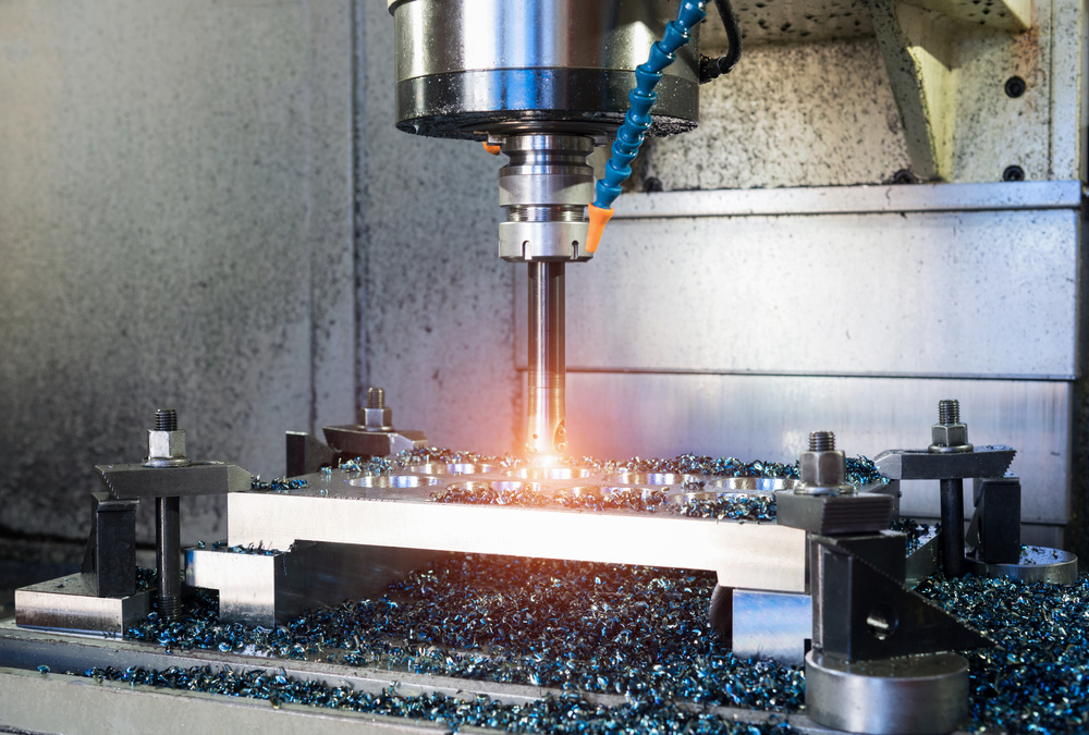
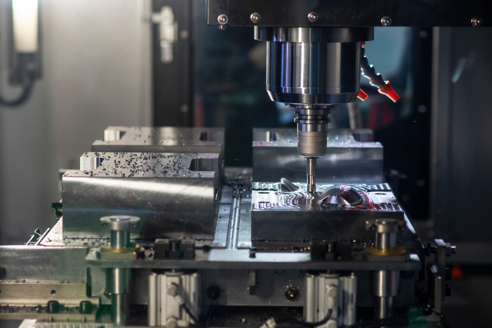
4.3 Production Machining
Once verified, the production machining process begins.
Machining Operations:
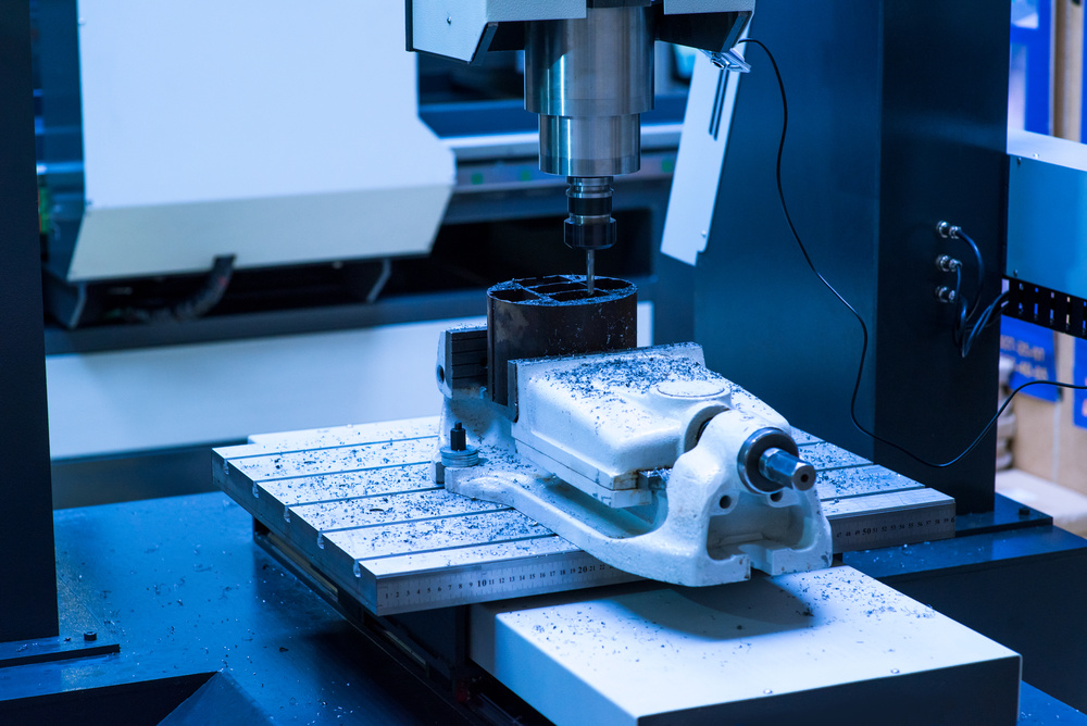
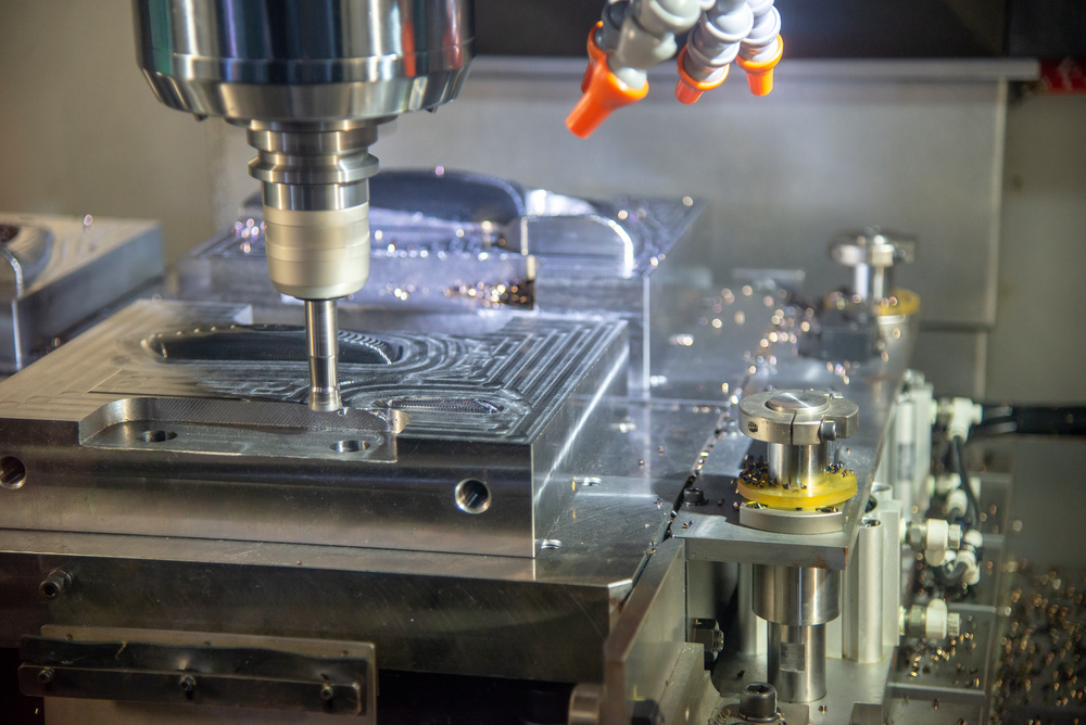
Milling Operations:
- Roughing: Remove large amounts of material quickly
- Finishing: Achieve final dimensions and surface finish
- Profiling: Create complex 2D and 3D shapes
- Pocketing: Create internal cavities and pockets
- Drilling: Create holes of various sizes and depths
- Tapping: Create internal threads
- Boring: Create precise holes with tight tolerances
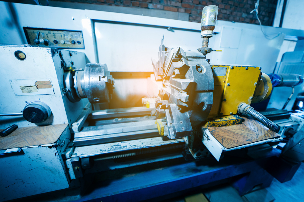
Turning Operations:
- Facing: Create flat surfaces on the end of workpieces
- Turning: Reduce diameter of cylindrical workpieces
- Grooving: Create grooves and recesses
- Threading: Create external threads
- Boring: Create internal diameters
- Parting: Separate finished parts from bar stock
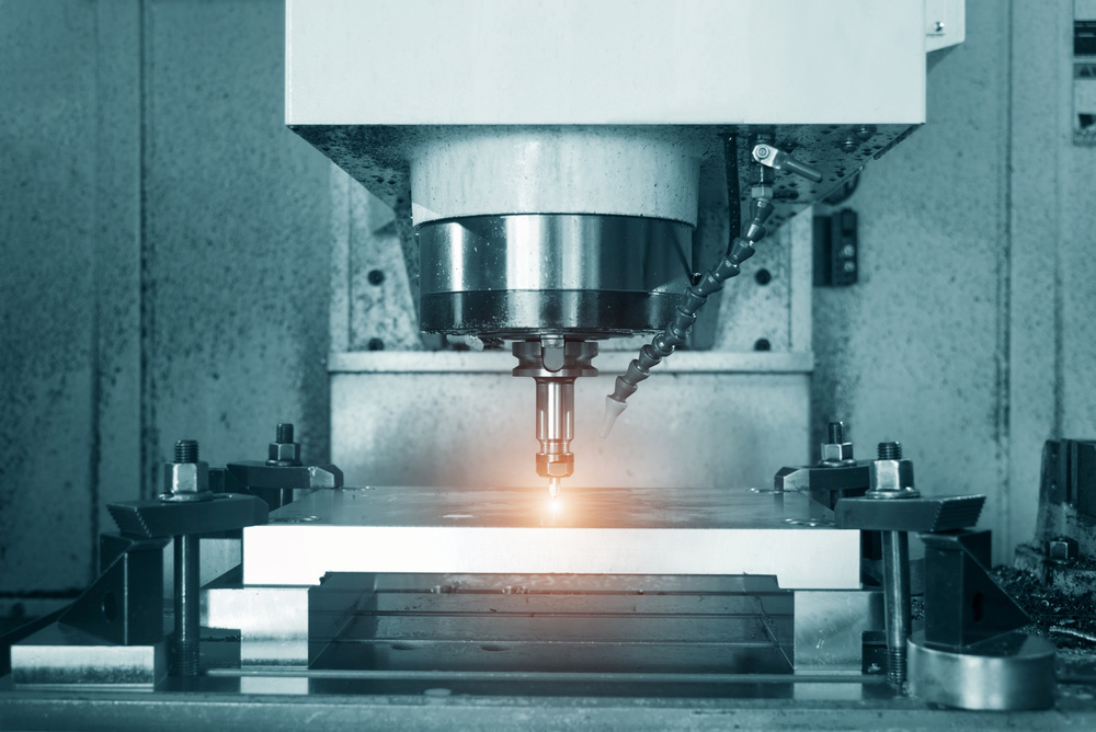
Advanced Machining Techniques:
- 5-Axis Machining: Simultaneous movement of five axes for complex geometries
- High-Speed Machining: Use of high spindle speeds and feed rates
- Swiss-Type Machining: Precision turning of small diameter parts
- Wire EDM: Electrical discharge machining for complex shapes
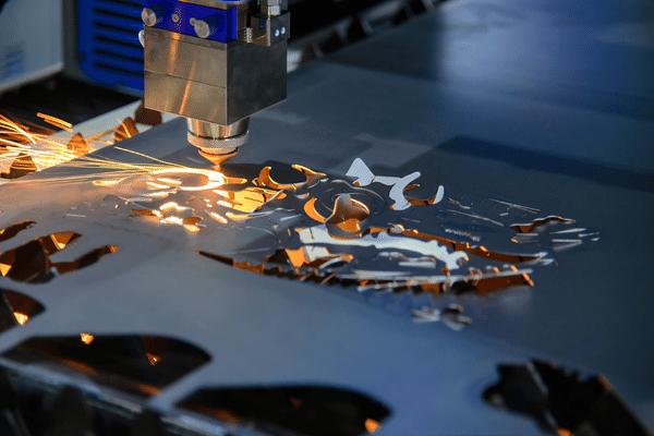
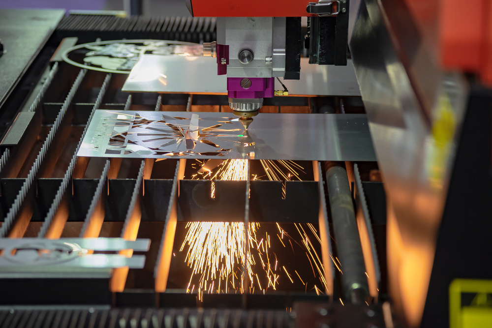
- Laser Machining: For precision cutting and engraving
4.4 In-Process Monitoring
Continuous monitoring during machining ensures consistent quality.
Monitoring Techniques:
- Visual Inspection: Observe cutting conditions and chip formation
- Sound Monitoring: Listen for unusual sounds indicating problems
- Vibration Analysis: Monitor vibration levels for process stability
- Force Monitoring: Measure cutting forces to detect tool wear
- Temperature Monitoring: Track spindle and workpiece temperatures
- Tool Wear Monitoring: Use sensors to detect tool wear and breakage
Process Control Strategies:
- Adaptive Control: Adjust cutting parameters in real-time based on conditions
- Statistical Process Control (SPC): Monitor process variation using statistical methods
- Real-Time Feedback: Use sensors to provide feedback to the control system
- Process Optimization: Continuously improve parameters based on monitoring data
5. Quality Control and Inspection
5.1 Dimensional Inspection
Thorough inspection ensures parts meet design specifications.
Inspection Tools and Equipment:
Hand Tools:
- Calipers: Digital and dial calipers for linear measurements
- Micrometers: External, internal, and depth micrometers
- Height Gages: For height measurements and layout
- Thread Gages: For thread verification
- Gage Blocks: For precision measurement standards
- Dial Indicators: For runout and position measurements
Advanced Measurement Systems:
- Coordinate Measuring Machines (CMM): 3D measurement of complex parts
- Vision Systems: Optical measurement for small features and complex geometries
- Laser Scanners: For 3D surface scanning and reverse engineering
- Roundness Testers: For measuring roundness and cylindricity
- Surface Roughness Testers: For measuring surface finish parameters
Inspection Process:
- First Article Inspection (FAI): Complete inspection of first production part
- In-Process Inspection: Periodic checks during production
- Final Inspection: Complete inspection of finished parts
- Statistical Sampling: Random sampling based on statistical methods
- Documentation: Record all inspection results
5.2 Surface Quality Inspection
Surface quality is critical for both functional and aesthetic requirements.
Surface Finish Parameters:
- Ra (Arithmetic Average): Most commonly used parameter
- Rz (Maximum Height): Maximum peak-to-valley height
- Rq (Root Mean Square): Root mean square average of deviations
- Rmax (Maximum Peak): Highest peak height
Surface Finish Measurement:
- Contact Profilometers: Stylus-based measurement
- Optical Profilometers: Non-contact optical measurement
- Interferometers: For very smooth surfaces
- Visual Inspection: Comparison with standard surface finish samples
Surface Finish Requirements by Industry:
- Aerospace: Typically Ra 0.4-1.6 μm for functional surfaces
- Medical: Ra 0.1-0.4 μm for implantable devices
- Automotive: Ra 0.8-3.2 μm for most components
- Electronics: Ra 0.4-1.6 μm for heat sinks and housings
5.3 Quality Assurance Documentation
Comprehensive documentation ensures traceability and quality control.
Documentation Requirements:
- First Article Inspection Reports (FAIR): Complete documentation of first part
- Process Control Records: Parameters and conditions during production
- Inspection Reports: Results of all dimensional and visual inspections
- Material Certifications: Material properties and traceability
- Non-Conformance Reports: Documentation of any deviations
- Corrective Action Reports: Actions taken to address quality issues
Quality Standards Compliance:
- ISO 9001: Quality management system
- AS9100: Aerospace quality standard
- IATF 16949: Automotive quality standard
- FDA Regulations: For medical devices
- NADCAP: Aerospace special processes
6. Post-Processing and Finishing
6.1 Deburring and Edge Preparation
Post-processing removes machining artifacts and prepares parts for final use.
Deburring Methods:
- Manual Deburring: Hand tools for precision deburring
- Mechanical Deburring: Brushes, grinders, and files
- Thermal Deburring: Use of thermal energy to remove burrs
- Chemical Deburring: Chemical solutions for burr removal
- Electrochemical Deburring: Electrical and chemical process
- Abrasive Flow Machining: Abrasive media through internal passages
Edge Preparation:
- Chamfering: Creating angled edges for safety and assembly
- Filleting: Creating rounded edges to reduce stress concentrations
- Edge Rounding: Removing sharp edges for handling safety
- Edge Blending: Creating smooth transitions between surfaces
6.2 Surface Treatment and Coating
Surface treatments improve appearance, functionality, and durability.
Common Surface Treatments:
Mechanical Finishing:
- Polishing: Creating smooth, reflective surfaces
- Grinding: Achieving precise dimensions and surface finish
- Honing: Improving surface finish and geometry of internal surfaces
- Lapping: Achieving ultra-precise surface finish and flatness
Chemical Treatments:
- Anodizing: Creating oxide layer on aluminum for corrosion resistance
- Electroplating: Applying metal coatings (chrome, nickel, gold)
- Electroless Plating: Chemical deposition of metal coatings
- Passivation: Improving corrosion resistance of stainless steel
- Chemical Conversion Coatings: Phosphate, chromate coatings
Thermal Treatments:
- Heat Treatment: Annealing, quenching, tempering
- Carburizing: Increasing surface hardness of steel
- Nitriding: Creating hard surface layer on steel
- Tempering: Reducing brittleness after quenching
Organic Coatings:
- Painting: Applying liquid paint coatings
- Powder Coating: Electrostatic application of powder materials
- E-coating: Electrostatic deposition of paint
- PVD Coating: Physical vapor deposition of hard coatings
6.3 Cleaning and Preparation for Delivery
Final cleaning ensures parts are ready for use or further processing.
Cleaning Processes:
- Solvent Cleaning: Using solvents to remove oils and contaminants
- Aqueous Cleaning: Using water-based solutions with detergents
- Ultrasonic Cleaning: Using ultrasonic energy for thorough cleaning
- Steam Cleaning: Using high-temperature steam for degreasing
- Vapor Degreasing: Using vaporized solvents for precision cleaning
Final Preparation:
- Drying: Ensuring parts are completely dry
- Packaging: Protecting parts during storage and shipping
- Labeling: Identifying parts with part numbers and specifications
- Documentation: Including all required certificates and documentation
7. Process Optimization and Continuous Improvement
7.1 Cycle Time Reduction
Optimizing cycle times improves productivity and reduces costs.
Optimization Strategies:
- Toolpath Optimization: Minimizing tool movements and air cuts
- Cutting Parameter Optimization: Finding optimal speed and feed rates
- Tool Selection: Using more efficient cutting tools
- Machine Utilization: Maximizing machine uptime
- Batch Processing: Grouping similar parts to reduce setup time
- Automation: Implementing automated loading and unloading
Cycle Time Analysis:
- Time Study: Measuring and analyzing each part of the process
- Bottleneck Identification: Finding and eliminating production bottlenecks
- Process Mapping: Documenting and analyzing the entire workflow
- Lean Manufacturing: Applying lean principles to eliminate waste
- Continuous Improvement: Implementing ongoing process improvements
7.2 Quality Improvement
Continuous quality improvement ensures consistent product quality.
Quality Improvement Methods:
- Root Cause Analysis: Identifying and addressing the root causes of quality issues
- Statistical Process Control (SPC): Using statistical methods to monitor and control processes
- Six Sigma: Implementing data-driven quality improvement
- Kaizen: Continuous improvement through small, incremental changes
- Poka-Yoke: Error-proofing processes to prevent defects
- Total Quality Management (TQM): Comprehensive quality management approach
7.3 Cost Reduction
Cost optimization is essential for maintaining competitiveness.
Cost Reduction Strategies:
- Material Optimization: Reducing material waste and improving yield
- Tool Life Extension: Maximizing tool performance and reducing tool costs
- Energy Efficiency: Reducing energy consumption
- Labor Optimization: Improving labor productivity
- Maintenance Optimization: Preventive maintenance to reduce downtime
- Supply Chain Optimization: Reducing costs through better supply chain management
8. Advanced Technologies and Future Trends
8.1 Industry 4.0 Integration
Industry 4.0 is transforming CNC machining through digitalization and connectivity.
Key Technologies:
- Internet of Things (IoT): Connecting machines and collecting real-time data
- Big Data Analytics: Analyzing large amounts of production data
- Artificial Intelligence (AI): Using AI for process optimization and predictive maintenance
- Digital Twin: Creating virtual replicas of machines and processes
- Cloud Computing: Storing and accessing data in the cloud
- Additive Manufacturing: Integrating 3D printing with CNC machining
Benefits of Industry 4.0:
- Increased Productivity: Improved machine utilization and process efficiency
- Better Quality: Real-time monitoring and predictive quality control
- Reduced Costs: Optimized processes and reduced downtime
- Flexibility: Quick changeover and adaptation to new products
- Traceability: Complete traceability of all production data
8.2 Automation and Robotics
Automation is increasing efficiency and reducing labor requirements.
Automation Technologies:
- Robotic Loading/Unloading: Automating workpiece handling
- Automatic Tool Changers: Reducing setup time and increasing machine utilization
- Pallet Systems: Enabling unattended machining
- Gantry Loaders: Handling large or heavy workpieces
- Collaborative Robots: Working safely alongside human operators
- Machine Tending Robots: Automating machine operation
Benefits of Automation:
- 24/7 Production: Unattended operation during non-working hours
- Consistency: Reduced human error and improved consistency
- Productivity: Increased machine utilization and throughput
- Safety: Reducing human exposure to hazardous conditions
- Labor Savings: Reducing labor costs and addressing skilled labor shortages
8.3 Advanced Materials and Processes
New materials and processes are expanding the capabilities of CNC machining.
Advanced Materials:
- Composite Materials: Carbon fiber, glass fiber composites
- Metal Matrix Composites: Metal matrix with ceramic reinforcements
- Additive Manufacturing Materials: Titanium, stainless steel, aluminum powders
- High-Performance Polymers: PEEK, PEI, PPS for demanding applications
- Metal Alloys: Advanced titanium, nickel, and aluminum alloys
Advanced Processes:
- Hybrid Manufacturing: Combining additive and subtractive processes
- Micro-Machining: Precision machining of small components
- High-Energy Processes: Laser machining, waterjet cutting
- Cryogenic Machining: Using liquid nitrogen for cooling
- Ultrasonic Machining: Using ultrasonic vibrations for material removal
Conclusion: The Complete CNC Machining Journey
The CNC machining process is a sophisticated and integrated workflow that transforms digital designs into physical components with exceptional precision and consistency. From initial design and programming to final inspection and delivery, each step plays a critical role in ensuring quality and efficiency.
Key Takeaways
Process Excellence:
- The CNC machining process requires careful planning and execution at every stage
- Quality control is essential throughout the entire manufacturing process
- Continuous improvement is necessary to maintain competitiveness
- Technology advancements are constantly expanding capabilities
Industry Impact:
- CNC machining is the backbone of modern manufacturing
- It enables the production of complex, high-precision components
- It supports a wide range of industries including aerospace, automotive, medical, and electronics
- It is evolving rapidly with Industry 4.0 and automation technologies
Future Outlook:
- Integration of AI and machine learning for process optimization
- Increased automation and robotics for improved productivity
- Expansion of Industry 4.0 technologies for connectivity and data analytics
- Development of new materials and processes for expanded capabilities
By understanding and mastering the complete CNC machining process flow, manufacturers can optimize their operations, ensure consistent quality, and stay competitive in an increasingly demanding global market.
Frequently Asked Questions (FAQ)
Q: What is the typical lead time for CNC machining?
A: Lead times vary based on complexity and volume, but typically range from 1-2 weeks for prototypes and 2-4 weeks for production runs.
Q: What tolerances can CNC machining achieve?
A: Standard CNC machining can achieve tolerances of ±0.005-0.01 mm, with high-precision machining capable of ±0.001-0.003 mm.
Q: What materials are commonly used in CNC machining?
A: Common materials include aluminum alloys, steel alloys, stainless steel, titanium, brass, copper, and various plastics and composites.
Q: How much does CNC machining cost?
A: Costs vary based on material, complexity, tolerance requirements, and volume. Prototype parts may cost (50-)500 each, while production parts can cost (1-)50 each depending on volume.
Q: What is the difference between 3-axis and 5-axis CNC machining?
A: 3-axis machines move along X, Y, and Z axes, while 5-axis machines add two rotational axes, enabling more complex geometries and reduced setup time.
Q: How do I choose the right CNC machining service provider?
A: Consider factors such as experience, equipment capabilities, quality certifications, lead times, pricing, and customer service.
Q: What is Design for Manufacturability (DFM) in CNC machining?
A: DFM is the practice of designing parts to optimize manufacturing efficiency, reduce costs, and improve quality.
Q: What are the environmental considerations for CNC machining?
A: Considerations include material waste reduction, coolant recycling, energy efficiency, and proper disposal of machining byproducts.
Q: How is CNC machining evolving with Industry 4.0?
A: Industry 4.0 is bringing IoT connectivity, AI optimization, digital twins, and advanced automation to CNC machining.
Q: What are the safety considerations for CNC machining?
A: Safety considerations include proper machine guarding, personal protective equipment, safe work practices, and regular equipment maintenance.
Disclaimer
- All information, opinions, and data contained in this article are for the purpose of information transmission only and do not constitute any advice on investment, transactions, law, medical care, or other matters.
- The content of the article is compiled based on public information or created based on the author’s personal understanding. Although every effort is made to ensure accuracy, it does not guarantee the completeness, accuracy, and timeliness of the information, nor does it bear any responsibility for any losses caused by the use of the content of this article.
- If the article involves third-party opinions, pictures, data, and other content, the copyright belongs to the original author. In case of infringement, please contact us for deletion.
- Readers should make independent decisions based on their actual situation and combined with professional opinions. The user shall bear all consequences arising from the use of the content of this article.
CNC Machining Process: Comprehensive Step-by-Step Guide
For more information on CNC machining services or to discuss your specific manufacturing requirements, contact our technical team today.
Contact Information:
- Phone: +86-18150097490
- Website: https://www.xmgoldcattle.com/