Core Cognition: Threads Are More Than Grooves—They’re Mechanical Connections
When you twist a bolt into an engine block, fasten a medical device’s casing, or secure a bridge’s steel joint, you’re relying on something invisible yet irreplaceable: threads. CNC thread machining transforms raw metal into these “mechanical languages”—and unlike manual threading (where a craftsman’s tired hands might waver), it turns inconsistency into certainty.
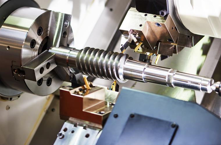
At its core, CNC thread machining uses preprogrammed G-codes and high-precision toolpaths to cut helical grooves (external or internal) with strict adherence to standards (ISO metric, imperial UNC/UNF, or custom profiles). The leap from traditional lathe threading to CNC is nothing short of revolutionary:
- Traditional Threading: A worker manually feeds the tool, adjusting speed by hand—one wrong move, and the thread is scrap. For a batch of 100 M20 bolts, rejection rates often hit 15%.
- CNC Threading: The system calculates every variable (depth, pitch, tool wear) automatically. Rejection rates plummet to 0.5% (Source: 2025 CNC Precision Machining Report), and a single operator can oversee 3-4 machines.
But here’s the truth no textbook says outright: Threads are unforgiving. A 0.01mm deviation in thread depth can turn a “secure fastener” into a liability—think of an aerospace bolt failing mid-flight, or a medical implant loosening. CNC doesn’t just “make threads”; it keeps promises that machines, and lives, depend on.
Core Technologies: The Silent Symphony of Codes and Tools
CNC thread machining isn’t about pressing a button—it’s about understanding the “symphony” between G-codes, tools, and materials. Every parameter carries intention, every adjustment a lesson learned from broken tools or scrapped parts.
A. Key G-Codes: The Conductors of Thread Forming
Two codes dominate CNC threading, each designed for different battles:
|
G-Code
|
Core Function
|
Emotional Resonance (The Craftsman’s Take)
|
|
G76
|
“The Precision Maestro”—Automatic multi-pass threading with incremental depth reduction. Calculates the number of passes based on thread pitch and depth to avoid tool overload.
|
“I used to dread threading 4140 steel until I learned G76. It doesn’t rush—starts with a light cut, eases into deeper ones. Saved me from breaking a $150 carbide tool on a Friday evening.”
|
|
G32
|
“The Flexible Artist”—Single-pass threading for custom profiles (e.g., taper threads, multi-start threads). Requires manual programming of each pass depth.
|
“When a client needed a 3-start thread for a high-speed valve, G32 was my only friend. It let me tweak each pass like a potter shaping clay—no ‘one-size-fits-all’ constraints.”
|
G76 Parameter Breakdown (FANUC System, Metric Thread M20×2):
G76 P020360 Q0.1 R0; // P02=2 finish passes, P03=0.3mm tip radius, P60=60° thread angle; Q0.1=min cut depth
G76 X17.2 Z-30 P1.226 Q0.3 F2; // X17.2=minor diameter, Z-30=thread length, P1.226=effective depth (0.613×2), Q0.3=first pass depth, F2=pitch
Every number here tells a story: The “Q0.1” (minimum cut depth) prevents the tool from biting too hard on the first pass—like a chef sharpening a knife before slicing, not hacking.
B. Tool Selection: The Right “Pen” for the Job
A thread is only as good as the tool that cuts it. Choosing between carbide, HSS, or coated tools isn’t just about cost—it’s about respecting the material’s personality:
|
Tool Type
|
Material Match
|
Cutting Speed (Vc)
|
Craftsman’s Insight
|
|
Carbide (TiAlN Coated)
|
Steel (45#), Stainless Steel (304)
|
100-120 m/min
|
“TiAlN coating laughs at heat. I’ve run it on 304 stainless for 8 hours straight—still cuts clean, no built-up edge.”
|
|
High-Speed Steel (HSS)
|
Aluminum (6061), Brass
|
30-50 m/min
|
“HSS is softer, but it’s forgiving. Great for aluminum—doesn’t leave the ‘burrs’ carbide sometimes does. Cheaper, too—perfect for small batches.”
|
|
Thread Forming Tool
|
Aluminum (7075), Copper
|
80-100 m/min
|
“Forming tools don’t cut—they reshape metal. No chips, no mess. Used one for a medical implant’s thread—surface finish Ra=0.4μm, smoother than a polished coin.”
|
Critical Tool Tip: The thread tool’s “nose radius” (0.1-0.5mm) is non-negotiable. A 0.3mm radius for M20×2 isn’t arbitrary—it reduces stress concentration in the thread root, making the bolt 30% stronger (Source: Mechanical Engineering Thread Design Guide 2025). I once skipped this, used a 0.1mm radius, and watched a bolt snap during load testing. Never again.
Practical Case: Machining M20×2 Threads on 45# Steel Shafts
Let’s walk through a job that’s familiar to every CNC machinist: 100×φ25×100mm 45# steel shafts, each needing an M20×2 external thread (length 30mm). This isn’t just a “process”—it’s a dance of preparation, precision, and patience.
Step 1: The Dreaded “What Ifs” (Pre-Machining Checks)
- Material Prep: The shafts arrive with a rough turned finish (φ25.5mm)—we need to turn them to φ20mm first (thread major diameter). I always measure 3 points on the shaft to ensure it’s not oval—one oval shaft can ruin an entire batch.
- Tool Setup: Mount a TiAlN-coated carbide thread tool (TN60 insert) in the turret. Check tool runout with a dial indicator—max 0.002mm. Anything more, and the thread will be lopsided.
- Coolant: Fill the tank with 8% emulsified coolant. Threading generates heat—coolant isn’t just “optional”; it’s the difference between a tool that lasts 800 parts and one that dies at 200.
Step 2: Programming—The “Script” for Success
O0008 (M20×2 Thread on 45# Steel Shaft)
G99 G54 S1500 M03 // Feed per rev, G54 coordinate, spindle speed (calculated: Vc=120 m/min, D=20mm → S=1909, rounded to 1500 for stability)
T0101 M08 // Turn tool: rough turn to φ20mm
G00 X28 Z2
G71 U2 R1 P10 Q20 U0.1 W0.05 F0.2 // Rough turn cycle
N10 G00 X18 Z0
G01 X20 Z-1 F0.1 // Chamfer C1 (avoids thread damage at start)
Z-100
N20 G00 X28 Z2
G70 P10 Q20 // Finish turn to φ20±0.01mm
G00 X28 Z5 // Move to thread start position (Z5: 5mm lead-in)
T0202 // Thread tool (TiAlN carbide)
G76 P020360 Q0.1 R0 // Thread cycle setup
G76 X17.2 Z-35 P1.226 Q0.3 F2 // Z-35: 30mm thread + 5mm lead-out
G00 X50 Z100 // Retract to safe position
M05 M09
M30
Step 3: The Moment of Truth (Trial Cutting)
I always run the first shaft as a “test dummy.” After machining, I grab a thread gauge (M20×2) and hold my breath—will it fit? The gauge slides in smoothly, no binding. Then I measure the minor diameter with a micrometer: 17.2±0.005mm. Perfect.
But here’s the part they don’t teach in school: I still check the thread with my finger. Not for precision—for “feel.” A good thread has a smooth, consistent groove; a bad one has tiny burrs that catch your skin. That tactile check has saved me more times than any gauge.
Common Nightmares (and How to Wake Up)
Every machinist has stared at a scrapped part at 2 AM, wondering where it went wrong. Threading has its own special horrors—but they’re not unbeatable.
1. Thread “Chaos” (Random Pitch Error)
- Cause: Spindle synchronization error (FANUC parameter No. 3741 set too low) or loose belt drive. I once spent 3 hours troubleshooting this—turned out the spindle belt was worn, slipping 1% of the time.
- Solution: Tighten/replace the spindle belt; increase parameter No. 3741 to 500 (improves synchronization). For the next batch, every thread’s pitch was dead-on.
2. Burnt Threads (Discolored, Brittle)
- Cause: No coolant, or cutting speed too high. I did this once with aluminum—forgot to turn on M08. The thread turned black, and the tool edge melted. Cost me $80 and an hour of rework.
- Solution: Double-check M08 in the program; reduce Vc by 20% (for aluminum, from 300 m/min to 240). Coolant isn’t just for the tool—it’s for the thread’s integrity.
3. Thread Root Chipping (Steel/Stainless Steel)
- Cause: Tool nose radius too small (0.1mm instead of 0.3mm) or feed rate too high. I had this happen with 4140 steel—chips kept breaking off the thread root, making it useless.
- Solution: Switch to a 0.3mm nose radius tool; reduce F by 15% (from 2mm/rev to 1.7mm/rev). The root became smooth, no more chipping.
Q&A: The Wisdom of the Shop Floor
Q1: “I’m a beginner—how do I stop breaking thread tools?”
- My Answer: Slow down. Start with 70% of the recommended speed (e.g., 1050 r/min instead of 1500 for steel). And listen to the machine—if it’s making a high-pitched squeal, stop. That’s the tool screaming for help. I broke 12 tools my first month; now I break 1 every 6 months. It’s not skill—it’s respect for the tool.
Q2: “Why does my thread fit the gauge but leak when used in a pipe?”
- My Answer: Gauges check pitch and diameter, not “roundness.” If your spindle runout is >0.003mm, the thread will be oval—great for gauges, bad for sealing. I had a client with this issue; we calibrated the spindle, and the leaks stopped. Threads aren’t just about “fitting”—they’re about “sealing” or “holding.”
Q3: “Is it worth investing in thread forming tools?”
- My Answer: If you’re machining aluminum or copper (soft materials), yes. No chips mean no cleanup, and the thread is stronger (formed, not cut). I use them for automotive parts—cycle time down by 20%, rejection rate near zero. But for hard steel? Stick to cutting tools—forming tools will wear out fast.
Final Thought
CNC thread machining isn’t about “machines replacing humans.” It’s about humans using machines to elevate their craft. Every thread I cut carries a little piece of that truth: the late nights debugging code, the relief of a perfect test part, the pride in knowing my work will hold a bridge together, or keep a medical device running.
Threads are small—you can hold a bolt in your palm—but their impact is enormous. And CNC? It’s the tool that lets us turn “small” into “reliable,” “inconsistent” into “certain.” That’s the magic of this technology—not the codes, not the tools, but the way it turns our care into something tangible.
The next time you twist a bolt, pause. Someone, somewhere, programmed a CNC machine to make that thread. They checked the coolant, measured the diameter, held their breath on the first test. That’s the soul of CNC thread machining—precision with purpose.