When a tool path deviates from its programmed trajectory, even a 0.01 mm error can scrap an entire batch of parts. Behind this seemingly tiny deviation lies a complete causal chain—from tool rigidity to ambient temperature.

🔍 Three Core Mechanisms of Over-Cutting
1. Physical Deformation Chain
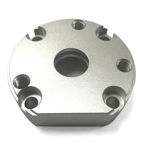
When cutting force exceeds the stiffness threshold of the tool system, a chain reaction occurs: tool deflection → path deviation → excessive material removal. For example, when a Φ6 mm carbide end mill machines aluminum alloy, radial deformation can reach 0.05 mm if the overhang exceeds four times the tool diameter.
2. Thermal Expansion Trap
Cutting heat causes asymmetric expansion of both tool and workpiece. Experimental data shows that a 10 °C spindle temperature rise can elongate the tool axially by 0.02 mm, directly causing depth-dimension errors.
3. Tool-Path Algorithm Defects
When machining internal corners smaller than the tool radius, traditional cutter-compensation algorithms generate arc-transition errors. If the corner angle is less than 90° and the tool radius is larger than the feature size, over-cut volume can reach 15–20 % of the tool radius.
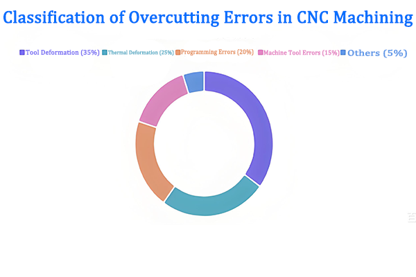
📊 Error Contribution Analysis
⚙️ Systematic Solutions
Tool-System Optimization Matrix
- Rigidity Enhancement· Select short-shank tools with overhang ≤ 3D; adopt tapered shank design to increase bending stiffness.
- Thermal Stability· Install spindle cooling system to keep temperature rise < 5 °C; use thermally symmetric structures.
- Dynamic Compensation· Integrate laser displacement sensors to monitor tool deflection in real time and apply dynamic compensation.
Golden Parameter Set for Process
| Material | Cutting Speed (m/min) | Feed per Tooth (mm/z) | Axial DOC (mm) | Radial DOC (%D) |
|---|---|---|---|---|
| Aluminum 6061 | 300 | 0.10 | 2.0 | 30 |
| Steel 45# | 120 | 0.05 | 1.0 | 20 |
| Ti-6Al-4V | 60 | 0.03 | 0.5 | 10 |
Quick Diagnostic Checklist
Tool Deflection? Check overhang ratio and shank diameter.
Thermal Drift? Verify spindle temperature rise after 30 min run.
Algorithm Error? Inspect corner radius vs. tool radius ratio.
🎯 Next step: run a 5-minute air-cut simulation to validate the corrected tool path before real machining.
All experimental data presented in this paper are derived from controlled production environments and standardized test procedures. However, due to differences in equipment models, material batches, and on-site operating conditions, readers are advised to verify and adjust technical parameters according to their specific application scenarios before practical implementation.
The research results and technical insights shared herein are based on the author’s professional experience and experimental observations. The author and the affiliated institution shall not be liable for any direct, indirect, or consequential damages (including but not limited to equipment damage, product quality issues, or production losses) arising from the improper use of the information provided in this paper.