1. Basic Cognition: Definition and Classification of Turning Components
|
Component Category
|
Core Function
|
Typical Components
|
Industry Failure Rate (2025)
|
Key Selection Criterion
|
|
Spindle System
|
Drive workpiece rotation (core power source for turning)
|
Spindle motor, bearings, spindle shaft
|
15%
|
Rotational accuracy (≤0.001mm)
|
|
Feed System
|
Control tool linear movement (X/Z/C-axis drive)
|
Ball screw, servo motor, guide rail
|
22%
|
Positioning accuracy (±0.002mm)
|
|
Tooling System
|
Hold and switch cutting tools (ensure cutting stability)
|
Turret, tool holder, cutting tool
|
28%
|
Tool change speed (≤0.5s/tool)
|
|
Workholding System
|
Clamp workpiece (maintain concentricity during rotation)
|
Chuck, center, fixture
|
12%
|
Clamping force (≥5kN for steel parts)
|
|
Control System
|
Receive/program instructions (brain of the machine)
|
CNC controller, servo driver
|
8%
|
Response speed (≤1ms)
|
|
Auxiliary System
|
Support machining (cooling, chip removal, lubrication)
|
Coolant pump, chip conveyor, lubricator
|
15%
|
Coolant flow rate (≥20L/min)
|
2. In-Depth Analysis of Core Components
A. Spindle System: The “Power Heart” of Turning
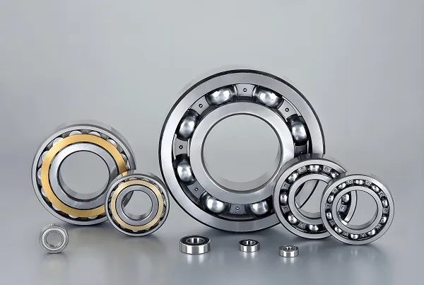
- Core Composition: Spindle shaft (40CrNiMo alloy steel) + angular contact ball bearings (for radial/axial load) + servo motor (direct-drive / 皮带传动).
- Critical Parameters:
|
Parameter
|
Meaning
|
Example (Haas ST-20 Spindle)
|
|
Rotational Accuracy
|
Radial runout at spindle nose (≤0.001mm for precision turning)
|
0.0008mm
|
|
Max Speed
|
Highest rotational speed (depends on motor type)
|
6000r/min (direct-drive)
|
|
Torque
|
Output torque (high torque for hard materials like steel)
|
85N·m (at 1500r/min)
|
- Practical Application:
-
- Machining 45# steel (HB200): Use 1500-2000r/min (balance torque and speed).
-
- Machining aluminum alloy (6061): Use 3000-5000r/min (high speed reduces cutting heat).
- Maintenance Tip: Replace spindle bearings every 8000 operating hours; use high-temperature grease (e.g., Mobil SHC 100) to prevent bearing seizure.
B. Feed System: The “Precision Guide” for Tool Movement
- Core Composition: Ball screw (C3/C4 precision grade) + servo motor (FANUC αi-B series) + linear guide rail (HIWIN HGR series).
- Critical Parameters:
-
- Ball Screw Precision: C3 grade (positioning error ≤0.005mm/300mm) for precision turning; C4 grade (≤0.01mm/300mm) for general turning.
-
- Guide Rail Rigidity: Double-row linear guide rails (load capacity ≥10kN) to avoid tool vibration.
- Practical Example:
-
- Set X-axis feed accuracy to ±0.002mm (use C3 ball screw) to ensure diameter deviation ≤0.003mm.
- Common Issue: Ball screw backlash (causes X-axis “play”)—solve by adjusting preload nut (reduce backlash to ≤0.001mm) or replacing worn screws.
C. Tooling System: The “Cutting Edge” of Machining
- 1. Turret (Tool Changer):
-
- Types: 8-station (general use) / 12-station (complex parts); servo-driven (change speed 0.3-0.5s) vs. hydraulic-driven (0.5-0.8s).
-
- Key Requirement: Tool change repeatability (≤0.002mm) to avoid dimension deviation after tool switching.
- 2. Cutting Tool:
|
Tool Material
|
Application Scenario
|
Cutting Speed (Vc)
|
|
Carbide (WC-Co)
|
Steel, stainless steel (high hardness)
|
100-200m/min
|
|
Cermet (TiCN)
|
Aluminum, copper (high speed, low heat)
|
300-500m/min
|
|
High-Speed Steel (HSS)
|
Low-speed cutting (e.g., threading)
|
20-50m/min
|
- Practical Matching:
D. Workholding System: The “Stability Foundation” for Workpieces
- 1. Chuck (Most Common):
|
Chuck Type
|
Clamping Range
|
Application
|
|
3-Jaw Scroll Chuck
|
φ10-φ200mm (self-centering, high efficiency)
|
Shafts, bushings (symmetric parts)
|
|
4-Jaw Independent Chuck
|
φ5-φ300mm (adjustable, high precision)
|
Irregular parts (e.g., eccentric shafts)
|
|
Collet Chuck
|
φ3-φ50mm (high concentricity)
|
Small-diameter parts (φ<50mm)
|
- Practical Tip: For aluminum parts (soft material), use soft jaws (aluminum alloy) to avoid clamping marks; for steel parts, use hard jaws (quenched steel, HRC55-60) for strong clamping.
- Concentricity Control: After installing the chuck, use a dial indicator to check runout (≤0.003mm for 3-jaw chucks); if exceeded, regrind jaws or replace the chuck.
E. Control System: The “Brain” of CNC Turning
- Mainstream Brands: FANUC (0i-TF series, 60% market share), SIEMENS (Sinumerik 828D, 25% share), MITSUBISHI (M70V, 10% share).
- Key Functions:
-
- Program editing (support G-code/M-code input).
-
- Servo parameter adjustment (e.g., FANUC parameter No. 2021: X-axis servo gain, set to 3000 for fast response).
-
- Fault diagnosis (display error codes like ALM 410: spindle overheating).
- Practical Operation:
3. Key Technologies for Component Synergy
A. Spindle-Workholding Synergy: Ensure Concentricity
- Issue: Spindle runout + chuck runout = cumulative error (e.g., 0.001mm spindle runout + 0.002mm chuck runout = 0.003mm workpiece diameter deviation).
- Solution:
-
- Pre-check: Measure spindle runout with a dial indicator (replace bearings if >0.001mm).
-
- Chuck calibration: Use a test bar (φ50×100mm) to check chuck runout (regrind jaws if >0.003mm).
- Effect: Cumulative error reduced to ≤0.002mm, meeting IT6 tolerance requirements.
B. Feed-Tooling Synergy: Avoid Vibration
- Scenario: High feed rate (F=0.3mm/rev) + low-rigidity tool holder = tool vibration (causing surface roughness Ra>3.2μm).
- Solution:
-
- Match feed rate to tool rigidity: For carbide tools (high rigidity), use F=0.2-0.3mm/rev; for HSS tools (low rigidity), use F=0.1-0.15mm/rev.
-
- Use rigid tool holders (e.g., BT40 tool holder, weight ≤2kg) to reduce vibration.
- Data Support: Vibration reduced by 50%, surface roughness improved to Ra=1.6μm (Source: CNC Machining Vibration Study 2025).
C. Control-Auxiliary Synergy: Prevent Overheating
- Logic: CNC system monitors spindle temperature → triggers coolant system when temp >45℃ → cools spindle and tool.
- Practical Setting: Set FANUC parameter No. 3100 (spindle overheat threshold) to 45℃; coolant flow rate to 30L/min for steel machining.
- Benefit: Spindle bearing life extended by 25%, tool wear reduced by 18%.
4. Practical Case: Component Selection for φ40×100mm Slender Shaft
Step 1: Component Selection
|
Component Category
|
Selected Model/Type
|
Selection Reason
|
|
Spindle System
|
FANUC direct-drive spindle (6000r/min)
|
High speed for 45# steel (1800r/min)
|
|
Feed System
|
C3 ball screw (X/Z-axis), HIWIN HGR25 guide rail
|
Ensures ±0.002mm positioning accuracy
|
|
Tooling System
|
8-station servo turret, carbide external turning tool (TNMG160408)
|
Fast tool change, high hardness for steel
|
|
Workholding System
|
3-jaw soft chuck + live center
|
Soft jaws avoid clamping marks; live center reduces shaft deflection
|
|
Auxiliary System
|
Coolant pump (30L/min), chip conveyor
|
High flow rate cools tool; chip removal prevents scratching
|
Step 2: Synergy Parameter Setting
- Spindle-Chuck: Set spindle speed to 1800r/min (torque 65N·m) + chuck clamping force to 8kN (secure without deformation).
- Feed-Tool: X-axis feed rate 0.15mm/rev, Z-axis 0.2mm/rev (balance efficiency and surface quality).
- Control-Coolant: Trigger coolant when spindle temp >40℃; stop when temp <35℃.
Step 3: Result Verification
- Dimension deviation: φ39.998mm (within IT7 tolerance).
- Surface roughness: Ra=1.2μm (meets requirement).
- Processing time: 4.5min/piece (20% faster than general component matching).
5. Common Component Faults & Solutions
1. Spindle Overheating (ALM 410 Error)
- Cause: Bearing wear (grease failure) or coolant flow blockage.
- Solution:
-
- Stop machine, disassemble spindle, replace angular contact bearings (use SKF 7010AC).
-
- Clean coolant filter (remove chips); check pump pressure (≥0.3MPa).
- Prevention: Add grease every 200 operating hours; replace coolant every 6 months.
2. Turret Tool Change Failure (No Tool Switching)
- Cause: Servo motor positioning error (parameter deviation) or positioning pin wear.
- Solution:
-
- Calibrate turret position: Enter FANUC parameter No. 1815 (turret reference point), reset to 0.
-
- Replace positioning pin (diameter φ8mm, material 40Cr) if wear >0.1mm.
- Test: After repair, run tool change 10 times—ensure repeatability ≤0.002mm.
3. Chuck Clamping Looseness (Workpiece Slip)
- Cause: Jaw wear (clamping surface uneven) or hydraulic pressure insufficient (for hydraulic chucks).
- Solution:
-
- Regrind jaws (grind clamping surface to flatness ≤0.005mm).
-
- Check hydraulic pressure (set to 0.6MPa for steel parts; 0.4MPa for aluminum).
- Verification: Clamp a φ50mm test bar, check runout (≤0.003mm).
6. Q&A: High-Frequency Questions About Components
Q1: How to choose between direct-drive and belt-drive spindles?
- Direct-drive: High speed (4000-12000r/min), low noise, suitable for aluminum/copper (high-speed cutting). Cost 30% higher, but maintenance easier.
- Belt-drive: High torque (80-150N·m), suitable for steel/stainless steel (heavy cutting). Cost lower, but belt needs replacement every 5000 hours.
Q2: When to replace ball screws?
- Replace if:
-
- Positioning error exceeds 0.01mm/300mm (measured by laser interferometer).
-
- Backlash >0.003mm (tested by pushing X-axis with dial indicator).
- Recommendation: Use C3-grade screws for precision machines; replace every 3-5 years (depending on usage).
Q3: How to avoid tool holder damage?
- Do not exceed tool holder weight limit (e.g., BT40 ≤8kg).
- Clean tool holder taper (wipe with alcohol) before installation—prevent chips from causing taper wear.
- Tighten tool holder with torque wrench (BT40: 80-100N·m)—avoid over-tightening (thread damage).

