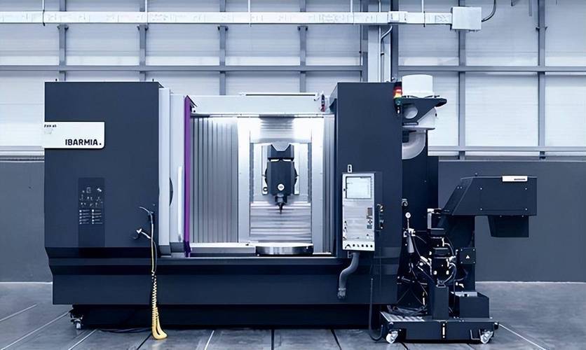
Step into a precision machining workshop in modern manufacturing, and amid the intermittent hum of metal cutting, Computer Numerical Control (CNC) machine tools have replaced the manual operation of traditional machines to become the “backbone” of production lines. Guided by digital instructions, they precisely control the relative movement between cutting tools and workpieces, transforming 3D models on design drawings into tangible parts step by step—from tiny precision components for medical devices to large-scale aero-engine parts, all rely on their “skilled hands.” The accuracy and efficiency of a CNC machine tool depend entirely on the “tacit cooperation” of its internal components; the design and role of each component directly influence the final machining results.
I. Core Components and Technical Characteristics
The components of a CNC machine tool are not just a random “pile of parts” but an integrated system designed around three core goals: “transmitting power effectively,” “performing movements accurately,” and “ensuring operational safety.” The technical details of each component determine the machine’s capabilities.
1. CNC System: The “Brain” of the Machine Tool
The CNC system acts as the “brain” of the machine tool, responsible for receiving machining instructions, processing information, and sending “operation signals” to other components. It not only interprets G-codes and M-codes generated by CAD/CAM software but also calculates the tool path in real time and corrects potential errors promptly.
Most modern CNC systems feature “multi-channel control”—take an auto parts production line as an example: a single machine can simultaneously control the spindle to cut a cylinder block while conveying the next workpiece to be processed, eliminating delays between processes and significantly improving efficiency. Some high-end systems are also equipped with AI compensation algorithms. For instance, during prolonged machining, the spindle may slightly “expand” due to heat; the system can automatically adjust cutting parameters based on data from temperature and vibration sensors, controlling dimensional errors within 0.002mm—roughly one-tenth the diameter of two human hairs.
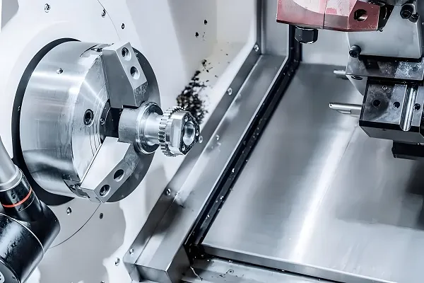
2. Spindle System: The “Core Hub” for Power Transmission
The spindle system is critical for “transmitting power” to the machine tool. It drives the cutting tool or workpiece to rotate at high speeds, and its stability, rigidity, and heat resistance directly affect the surface smoothness of the machined part.
- Speed: The maximum speed of the spindle in a standard CNC lathe is approximately 3,000–6,000 rpm, which is sufficient for machining conventional steel and cast iron parts. However, for precision molds (e.g., mobile phone case molds), high-speed milling machines can achieve spindle speeds exceeding 20,000 rpm, enabling efficient cutting of aluminum alloys, titanium alloys, and other difficult-to-machine materials with fast and smooth results, leaving no rough marks.
- Rigidity Design: Spindle units often use “ceramic bearings” or “electric spindles.” Ceramic bearings have a friction coefficient only one-third that of traditional steel bearings, minimizing vibration during high-speed rotation. Electric spindles integrate the motor and spindle into one unit, eliminating errors caused by belt drives and achieving a positioning accuracy of 0.001mm—equivalent to the diameter of a fine grain of sand.
- Heat Control: Some spindles are equipped with constant-temperature oil cooling or water cooling systems, which limit spindle temperature rise to within 2°C. Without such systems, prolonged high-speed rotation would cause the spindle to “expand and deform,” leading to inaccurate part dimensions. With temperature control, consistent dimensional accuracy is maintained even during long machining cycles.
3. Feed System: The “Executive Hands and Feet” for Precision Control
The feed system acts as the “hands and feet” of the machine tool, driving the worktable or cutting tool to move according to instructions. Its performance directly determines machining accuracy and consists mainly of servo motors, ball screws, and guideways.
- Servo Motors: Permanent magnet synchronous servo motors are used for their rapid response, achieving a positioning accuracy of 0.0001mm—roughly one-thousandth the diameter of a human hair. They avoid “overshoot” (exceeding the target position and then retracting) during machining.
- Ball Screws: As key components for power transmission, their pitch error directly affects movement accuracy. High-end machines use a “pre-tensioning” installation process to reduce deformation of the screw during high-speed movement. Some machines also install linear scales on the screws to feed back position information in real time, forming a “closed-loop control” system that further corrects errors.
- Guideways: There are two main types: rolling guideways and sliding guideways. Rolling guideways have an extremely low friction coefficient (0.001–0.005), reducing energy consumption during machine operation and improving the stability of worktable movement, thus avoiding uneven machining marks caused by inconsistent friction.
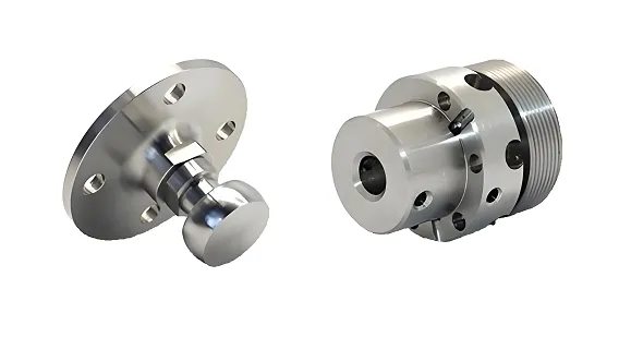
4. Tool System: The “Tool Terminal” in Direct Contact with Workpieces
The tool system is the “tool terminal” that directly contacts and cuts the workpiece, consisting of tool holders, tool bodies, and tool clamping devices. Its material and structure are selected based on the properties of the workpiece material.
- Tool Holders: Standardized interfaces such as HSK or BT tool holders are used to ensure coaxiality between the tool holder and spindle, minimizing clamping errors. Some tool holders include built-in “dynamic balancing modules” to offset unbalanced forces during high-speed rotation, preventing tool wear and uneven workpiece surfaces.
- Tool Bodies: These are designed for specific machining needs. For example, “carbide-coated tools” (usually with a TiAlN coating for enhanced wear resistance) are used for stainless steel, while diamond tools are suitable for composite materials (e.g., carbon fiber parts) to avoid fiber fraying.
- Tool Clamping Devices: These include tool magazines and automatic tool changers (ATCs). A tool magazine can store 10–120 different tools, and an ATC can complete a tool change in as little as 0.5 seconds. This enables “one-time clamping, multi-process machining”—e.g., milling, drilling, and tapping can be performed continuously without stopping to change tools, reducing errors caused by repeated workpiece clamping.
5. Auxiliary Devices: The “Support System” for Stable Machining
Although auxiliary devices do not directly cut the workpiece, they are essential for smooth machining. They mainly include cooling systems, chip removal devices, and protective systems.
- Cooling Systems: These use cutting fluid or compressed air to cool the tool and workpiece. Sufficient cooling extends the service life of carbide tools by up to 30% and flushes away metal chips to prevent them from scratching the workpiece surface.
- Chip Removal Devices: Chain-type or screw-type chip conveyors are commonly used to remove chips promptly. For example, during mass production of auto bolts, accumulated chips can jam the machine—chip removal devices enable 24/7 continuous operation.
- Protective Systems: Most machines use fully enclosed guards to prevent cutting fluid splashes (which wet the floor and pose safety risks to operators) and block dust, reducing wear on guideways and ball screws and extending the machine’s service life.
II. Core Functions and Practical Application Value
CNC machine tools are not just “accurate cutters”; their core advantage lies in solving challenges that traditional machines cannot address—such as machining complex parts and ensuring consistency in mass production. These functions rely entirely on the “tacit cooperation” of components.
1. Multi-Axis Machining: Breaking the Bottleneck of Complex Surface Machining
Multi-axis machining—one of the most “powerful” functions of CNC machines—involves simultaneous movement of multiple axes (typically 3, 4, or 5 axes) to create complex tool paths.
Traditional 3-axis machines (X, Y, Z axes) can only machine flat or simple curved surfaces. However, for parts like aero-engine blades (with uneven “free-form surfaces”), 3-axis machines cannot reach certain angles. This is where 5-axis machines excel: they add A and C axes to rotate the workpiece, ensuring the tool always contacts the cutting surface at the optimal angle. The resulting blade surface roughness can reach Ra 0.8μm (almost imperceptible to the touch), and processes that previously required 3 separate machines can now be completed with “one-time clamping,” shortening the machining cycle by over 40%.
2. High-Precision Positioning and Repeatability: Ensuring Consistency in Mass Production
The positioning accuracy of CNC machines (the deviation between the commanded and actual positions) is 0.001–0.005mm, and their repeatability (deviation when returning to the same position multiple times) is even higher at 0.0005–0.002mm—far exceeding the 0.05mm positioning accuracy of traditional manual machines (a 10-fold difference).
For example, the bolt holes in an auto engine cylinder block require extreme precision to avoid jamming during bolt installation. CNC machines control the hole position deviation of each cylinder block to within 0.003mm; even after machining 1,000 cylinder blocks, the hole positions remain nearly identical, minimizing scrap rates.
3. Automation and Flexible Production: Adapting to High-Mix, Low-Volume Needs
CNC machines can be integrated with robots, loading/unloading mechanisms, and MES (Manufacturing Execution System) software to achieve “unmanned machining” and flexible production—ideal for the “high-mix, low-volume” trends in modern manufacturing.
- Automation: In new energy vehicle battery casing production, robots automatically load/unload workpieces and cooperate with ATCs to enable 24/7 operation of a single machine—improving efficiency by over 50% compared to manual operation.
- Flexibility: Changing production tasks only requires modifying the CNC program, no need to replace the entire machine or reconfigure fixtures. For example, a single CNC lathe can machine auto half-shafts in the morning and motorcycle crankshafts in the afternoon, offering exceptional flexibility.
4. Real-Time Monitoring and Intelligent Compensation: Addressing Variables During Machining
Some high-end CNC machines are equipped with “machining condition monitoring systems,” which use sensors to track real-time data (e.g., spindle load, cutting vibration, tool wear). The CNC system then uses algorithms to make automatic adjustments—correcting issues promptly even if small anomalies occur during machining.
For example, when machining high-strength steel, slight tool wear increases spindle load; sensors detect this change, and the system automatically reduces feed rate to prevent tool breakage. If workshop temperature rises (causing guideway deformation), the system uses a preconfigured “temperature-error model” to adjust the feed axis position automatically, offsetting deformation-induced errors and ensuring part accuracy.
III. Synergy Logic Between Components and Functions
The performance of a CNC machine tool is not simply the “sum of component performance” but depends on their “collective effort.” For multi-axis machining, three key steps are required: first, the CNC system must accurately calculate the speed and angle of each axis (no delays allowed); second, servo motors must “obey commands” and respond immediately (no lag); finally, ball screws and guideways must ensure precise axis movement (no deviation). A failure in any step—e.g., a 0.001-second delay in the CNC system or slow servo motor response—will cause tool path deviation and scrap the part.
Similarly, high-precision positioning requires not only accurate servo motors and ball screws but also sufficient spindle rigidity. If the spindle lacks rigidity, it will “bend” under cutting forces; even if the feed system positions the workpiece accurately, spindle deviation will still lead to machining errors.
IV. FAQs About CNC Components
- How to determine if the servo motor of the CNC system is faulty?
Pay attention to the motor’s operating status: abnormal “hum” noises or increased vibration (detected by hand) may indicate a problem. Check the drive for alarm codes (e.g., “ALM” or “ERR”)—these usually confirm motor or drive faults. Additionally, use a tachometer to compare the actual motor speed with the commanded speed; a large discrepancy also signals a potential fault.
- What are the key daily maintenance tasks for ball screws?
First, regularly clean iron chips and dust from the screw surface to prevent debris from getting stuck between the screw and nut. Second, apply lubricating grease every 100 operating hours to avoid wear. Finally, check the fit clearance between the screw and nut periodically; if looseness is detected, adjust the preload device to maintain transmission accuracy.
- How to troubleshoot inaccurate positioning of a CNC turntable?
First, check the encoder feedback signal—intermittent signals may indicate poor wiring connections. Next, inspect the turntable’s transmission components (e.g., gears, belts) for looseness or wear. Then, recalibrate the turntable’s zero position (e.g., use a dial indicator to measure zero-position deviation). Finally, verify CNC system parameters (e.g., compensation values)—correcting parameter errors can also fix positioning issues.
- What are common faults of Automatic Tool Changers (ATCs)?
The most frequent issue is the tool magazine failing to locate the correct tool position—caused by a faulty magazine positioning motor or inaccurate tool position sensor. Another common problem is the ATC gripper failing to hold the tool, usually due to worn grippers or insufficient air/hydraulic pressure. Additionally, the ATC may get stuck during tool changes—this often results from worn bearings in the gripper or missing position signals from the CNC system. To resolve these issues, first inspect the relevant mechanical components, then check the power system (air/hydraulic) and electrical signals—most problems can be fixed with this approach.
Disclaimer
- All information, opinions, and data contained in this article are for the purpose of information transmission only and do not constitute any advice on investment, transactions, law, medical care, or other matters.
- The content of the article is compiled based on public information or created based on the author’s personal understanding. Although every effort is made to ensure accuracy, it does not guarantee the completeness, accuracy, and timeliness of the information, nor does it bear any responsibility for any losses caused by the use of the content of this article.
- If the article involves third-party opinions, pictures, data, and other content, the copyright belongs to the original author. In case of infringement, please contact us for deletion.
- Readers should make independent decisions based on their actual situation and combined with professional opinions. The user shall bear all consequences arising from the use of the content of this article.
Author:

Name: Dr. Benjamin Keller
Nationality: Germany
Titles: Senior Research Scientist, Industrial Technology Consultant
Work Experience and Industry Qualifications:
An expert in the CNC field from Germany, with 25 years of in – depth industry experience. He has long focused on the high – precision optimization of five – axis linkage machining technology, the intelligent upgrade of AI – driven numerical control systems, and the practical application of digital twins in machining scenarios. He is particularly good at solving machining technical problems of complex surfaces in aerospace and precision components in the medical field. He is proficient in advanced programming of G – code and M – code, and is skilled in the debugging and optimization of mainstream numerical control systems such as Fanuc and Siemens. He can build an adaptive model of cutting parameters through machine learning algorithms, use virtual simulation tools to pre – rehearse the machining process and perform error compensation. At the same time, he has the ability to integrate multi – axis machining processes and additive manufacturing technologies, which can effectively improve machining efficiency and precision consistency.