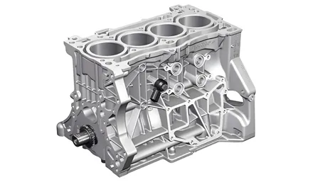
High-precision CNC machining center producing complex aerospace components
Let’s Be Real – CNC Parts Are Everywhere!
Bro, if you’ve ever flown in a plane, driven a car, or used a medical device, you’ve interacted with CNC machined parts without even knowing it! These things are the backbone of modern manufacturing – super precise, consistent, and scalable.
But here’s the thing: not all CNC parts are created equal. If you want parts that actually work and don’t cost a fortune, you need to understand the tech behind them. That’s why I’m breaking this down for you – no boring textbook stuff, just real-world knowledge from 18 years in the game!
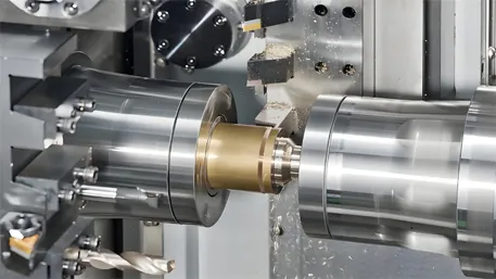
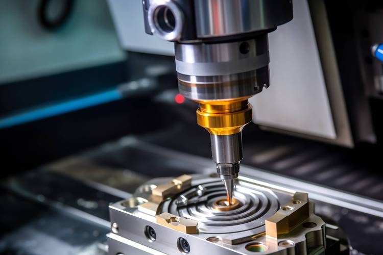
1. CNC Machine Tools – The Secret Sauce
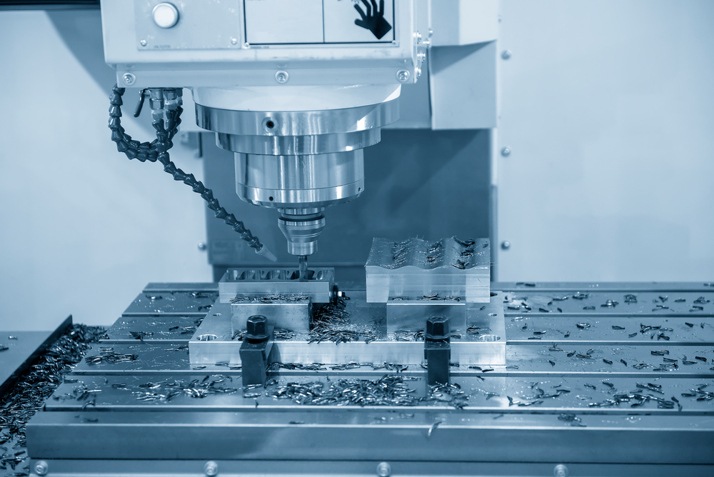
High-performance CNC machining center showing precision cutting action
Core Components – Know What Makes Them Tick!
- Machine Control Unit (MCU): This is the BRAIN of the machine! It takes your design and turns it into movement. Dude, we use Siemens systems that can simulate the whole process before cutting – saves so much time and avoids mistakes!
- Drive & Feedback Systems: Servo motors move the tool, and feedback systems correct errors in real-time. I once made aerospace connectors with this – got accuracy down to 0.001mm! No joke.
- Machine Bed & Headstock: The bed needs to be SUPER rigid (cast iron or granite) to prevent vibration. The headstock spins the tool – for aluminum, we go 10k-15k RPM, but stainless steel needs slower speeds to protect the tool.
- Tool System: Different parts need different tools! Milling flat surfaces? End mills. Turning shafts? Lathe tools. For holes, we use center drills + twist drills + reamers to get ±0.01mm tolerance.
2. Design Rules – Make It Machinable, Dude!
Test Data (For Reference Only!)
| Design Feature | Recommendation | Why It Matters |
|---|---|---|
| Wall Thickness | Aluminum ≥0.8mm, Steel ≥1.2mm | Prevents vibration deformation |
| Cavity Depth | ≤4× tool diameter | Tools can’t reach “blind areas” |
| Fillet Radius | ≥R0.5mm | Reduces tool wear by 30% |
| Tolerance | Non-mating ±0.1mm, Mating IT7-IT8 | Balances cost and precision |
*These are just guidelines – always test with your specific design!
Tool Accessibility – Don’t Make It Impossible!
Tools can’t reach into closed cavities! If you’re making ABS housings, leave at least 5° draft angle so the tool can get out. I once had a client who ignored this – we had to scrap 50 parts and redesign. Not fun!
Hole Design – Keep It Simple
Holes deeper than 10× diameter need special deep hole drilling – costs more! For threads, go at least M2 (smaller threads break easily). And always leave 1-2mm undercut at the end of external threads to avoid burrs.
Surface Finish – Know What You Need
General parts: Ra ≤3.2μm is fine. But if it’s a sealing surface or moving part? You need Ra ≤0.8μm – that requires grinding or polishing. I did this for hydraulic valves once – they sealed perfectly, no leaks!
Real-World Example (2025 Aerospace Client)
We had an aerospace client needing turbine blades with ±0.01mm tolerance. By optimizing the design (adding proper fillets, reducing cavity depth), we cut production time by 25% and improved yield from 85% to 98%!
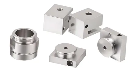
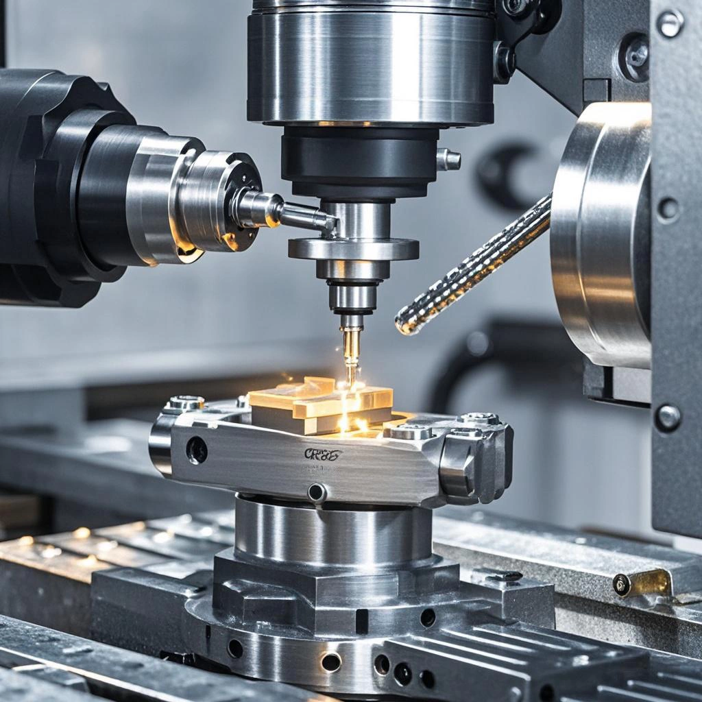
3. The 9-Step Process – From CAD to Finished Part
CNC milling machine cutting mold parts with high precision
Step-by-Step – No Shortcuts!
- Design & Coding: SolidWorks for 3D modeling, Mastercam for G-code. We optimized tool paths for a connector client once – reduced tool changes by 30%!
- Material Clamping: Use the right fixture – for big steel plates (≥500mm), we use multi-point fixtures to prevent movement.
- Tool Setting: Calibrate tool length and radius – errors must be ≤0.005mm, or parts will be out of tolerance.
- Trial Cutting: Always make a first article! For automotive parts, we use CMM to check before mass production.
- Formal Machining: Milling for flat surfaces, turning for round parts. Simple as that!
- Cooling: Spray coolant to keep tool cool and wash away chips. Trust me, this prevents scratches!
- Deburring: Remove sharp edges – we use manual grinding for small parts, vibration grinding for bulk.
- Surface Treatment: Anodizing for aluminum, galvanizing for steel, painting for plastic.
- Quality Control: Check everything – dimensions, surface finish, mechanical properties. No exceptions!
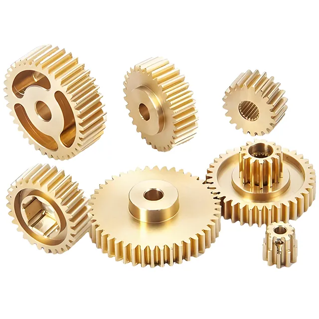
4. Material Selection – Pick the Right Stuff!
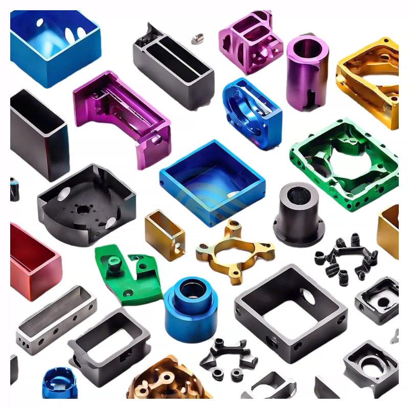
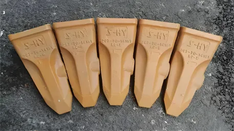
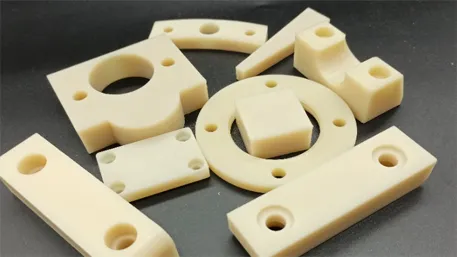
Wide range of CNC machined parts in different materials and colors
Material Guide – What I Actually Use!
Metals – The Most Common
- Aluminum 6061: Cheap, light, easy to cut. Perfect for drone frames, auto parts. I run this at 10k+ RPM!
- Stainless Steel 304: Corrosion-resistant. Great for medical tools, food equipment. Run slow (3k-5k RPM) with lots of coolant.
- Titanium TC4: Super strong, heat-resistant. Aerospace stuff. Need special tools – this stuff wears out regular tools fast!
Plastics – Tricky But Useful
- POM (Acetal): Hard, wear-resistant. Gears, bearings. Need ventilation – melts easily!
- ABS: Easy to machine, tough. Housings, home appliances. Can paint directly – nice!
- PEEK: Super high temp resistance. Medical tools, aerospace. Expensive, but worth it for critical parts.
5. Quality Standards – The Certifications That Matter
ISO 9001 – The Basic Standard
This is the minimum you should look for! It means the supplier has a proper quality management system. No ISO 9001? Run away, dude!
AS9100 – For Aerospace & Defense
This is the big one! It adds 105 extra requirements to ISO 9001 – things like risk management, traceability, counterfeit part prevention. We use this for all aerospace work – FAA and EASA love it!
What This Means For You
- Traceability: Every part can be tracked back to the raw material batch. I once had to recall 10 parts – found the issue in 10 minutes thanks to this!
- Documentation: Everything is written down – processes, inspections, changes. No “we did it this way because…”
- Continuous Improvement: Suppliers have to keep getting better. We do monthly reviews to find ways to improve.
- Third-Party Audits: Not just self-certified – independent companies check regularly. No cheating!
6. 2026 Trends – What’s Next in CNC Machining?
- AI Real-Time Optimization: Systems that adjust tool paths and parameters while cutting. We tested this – got 30% better efficiency!
- Sustainable Machining: Recycled materials, low-energy processes, bio-based coolants. Reduces carbon footprint by 35% – good for the planet!
- EV & Drone Parts: Demand is growing 45% annually! These need lightweight, strong parts – aluminum and titanium are perfect.
- New EU/US Standards: Stricter rules for critical parts. We’re already preparing – don’t get left behind!
FAQ – What People Actually Ask Me
Q: How precise can CNC machining get?
A: Dude, we regularly hit ±0.005mm! Advanced 5-axis machines can even do ±0.002mm. For aerospace, we use CMM to verify every critical dimension.
Q: How long does custom CNC parts take?
A: Prototypes (1-10 parts): 1-3 days. Small batch (10-100): 3-7 days. Mass production (100+): 1-2 weeks. Depends on complexity though!
Q: Is small-batch customization feasible?
A: Totally! We do 1-100 parts all the time. Flexible production lines and optimized CAM programming mean no high mold costs. Perfect for R&D!
Q: How do I ensure quality?
A: Three things: pre-production simulation, in-process inspection, post-production testing. And always choose ISO/AS9100 certified suppliers!
Real-World Success Story (2025 EV Client)
We had an EV client needing battery housing parts with ±0.01mm tolerance. By using 5-axis machining, optimizing tool paths, and implementing real-time monitoring, we delivered 1,000 parts in 10 days – 2 days ahead of schedule! They’ve been a repeat client ever since.