I. Underlying Technical Architecture and Machine Tool System of Turning Machining
(A) Classification of Machine Tools and Core Performance Indicators
Turning equipment can be categorized by structural form into:
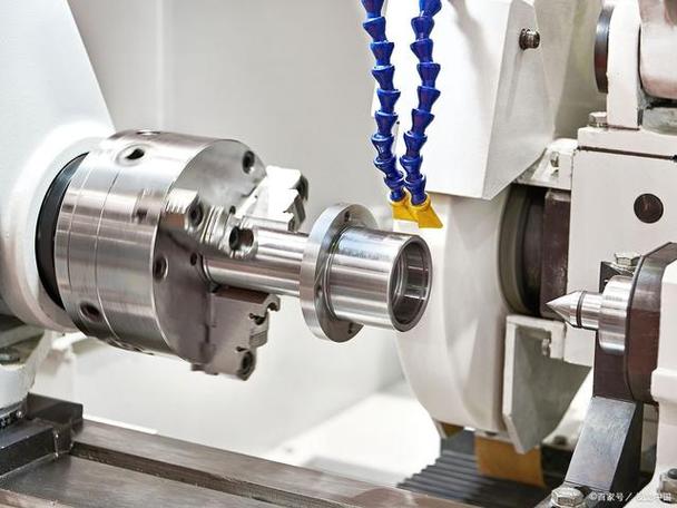
- Horizontal Lathes: Accounting for over 75% of applications, suitable for long shaft-type parts. Typical models include the MAZAK INTEGREX i-500 AM (spindle power 37kW, torque 1100N·m, positioning accuracy ±2μm);
- Vertical Lathes: Used for disc-type parts with diameters ≥1000mm, such as the CK5120 vertical lathe (maximum machining diameter 2000mm, load capacity 10 tons);
- Swiss-Type Lathes: Preferred for precision micro-parts, e.g., STAR SR-38J (spindle speed 8000r/min, X/Z axis feed rate 20m/min).
Key Performance Parameters:
- Spindle rotational accuracy: ≤1μm for precision grade (ISO 230-7 standard);
- Guideway straightness: ≤0.002mm/1000mm horizontally, ≤0.003mm/1000mm vertically;
- Tool turret change time: ≤0.8 seconds for hydraulic drive, ≤0.4 seconds for servo drive.
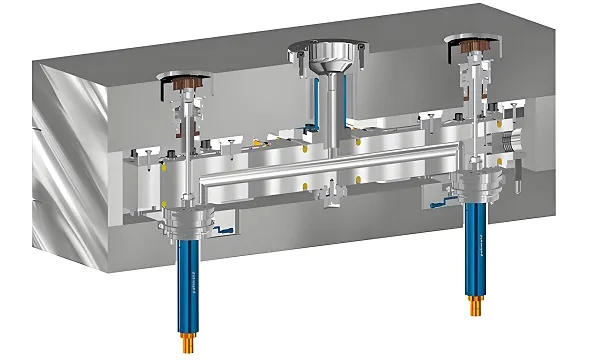
(B) CNC Systems and Intelligent Control Technologies
Mainstream CNC systems like FANUC 30i-MODEL B (supporting nanometer-level interpolation) and SIEMENS 840D sl (built-in AI cutting optimization module) feature:
- Five-axis simultaneous machining (RTCP real-time tool center point control);
- Thermal deformation compensation system (temperature sensor spacing ≤500mm, compensation accuracy ±2μm);
- Tool life management module (wear prediction via vibration spectrum analysis, accuracy ≥92%).
II. In-Depth Deconstruction of the Turning Process System (10 Major Processes + 21 Sub-Processes)
(A) Basic Shaping Process Cluster
1. Cylindrical Turning Engineering Chain
- Rough Turning: Uses large depth of cut (ap=3-5mm) and high feed rate (f=0.3-0.8mm/rev), with material removal rate up to 800cm³/min and surface roughness Ra 12.5-3.2μm;
- Finish Turning: Employs PCBN tools (cutting speed Vc=150-300m/min), tolerance control ±0.005mm, Ra≤0.8μm;
- Ultra-Precision Turning: For optical components, uses air-static spindles (speed ≤1000r/min) and diamond tools to achieve mirror finishes with Ra≤0.05μm.
Application Cases:
- Aero-engine turbine shaft (material Inconel 718): 0.5mm roughing allowance, three finish turning passes, final dimension φ50±0.003mm, roundness ≤2μm;
- Automotive steering knuckle shaft (material 42CrMo): Uses stepped turning to complete φ30/φ45/φ60mm three-section shaft in one setup, coaxiality error ≤0.008mm.
2. Technical Specifications for Face Machining
- Flatness Control: Monitored in real time with an electronic level, flatness ≤0.005mm per 100mm side;
- Perpendicularity Assurance: Ensures end face-axis perpendicularity ≤0.002mm/100mm via spindle axial runout detection (≤1μm) and tool perpendicularity calibration (angle gauge accuracy ±5”).
(B) Precision Engineering for Hole System Machining
3. Deep Hole Drilling Technology (L/D≥5)
- BTA Deep Hole Drilling: Suitable for φ12-φ150mm holes, coolant pressure 3-20MPa, straightness ≤0.3mm/m;
- Gun Drilling Process: Machines φ3-φ20mm deep holes (L/D≤30), hole deviation ≤0.15mm/100mm, surface roughness Ra≤3.2μm.
Case: Hydraulic cylinder barrel (material 20# steel, φ80×1500mm): Machined in two BTA drilling segments (800mm + 700mm), coaxiality at joint ≤0.02mm.
4. Precision Boring Process Package
- Single-Edge Boring Tool: For IT7-grade holes, tip radius R0.2-0.8mm, cutting speed Vc=50-120m/min;
- Double-Edge Floating Boring Tool: Self-centering, IT6-grade tolerance, roundness ≤1μm, ideal for mass production (e.g., engine cylinder bore φ85H6).
(C) Thread Manufacturing Technology System
5. Tapping Process Parameter Matrix
| Material Type | Thread Specification | Cutting Speed Vc (m/min) | Feed Rate f (mm/rev) | Cooling Method |
|---|---|---|---|---|
| Aluminum Alloy | M10×1.5 | 8-12 | 1.5 | Vegetable Cutting Oil |
| Stainless Steel | M16×2 | 3-5 | 2.0 | Internal Coolant (5%) |
| Titanium Alloy | M8×1 | 2-3 | 1.0 | Minimum Quantity Lubrication (MQL) |
6. High-Speed Thread Cutting Technology
- Carbide Whirlwind Milling Cutter: 3-5× faster than conventional turning, suitable for trapezoidal threads (Tr40×7), surface roughness Ra≤1.6μm;
- Multi-Start Thread Machining: Achieves three-start threads (lead 9mm) in one pass via electronic gear ratio (e.g., 3:1) between spindle and tool, pitch cumulative error ≤0.005mm/100mm.
(D) Surface Engineering and Special Processes
7. Standardized Knurling Process Flow
- Pre-Machining Requirements: Surface roughness Ra≤6.3μm before knurling, diameter Reserve expansion amount 0.1-0.3mm (modulus-dependent);
- Process Parameters: Modulus m=0.5-1.2, knurling wheel pressure 10-30kN, feed rate f=0.8-1.5mm/rev, surface hardness increased to HV300-500.
8. Micro-Grooving Technology
- Tooling: Uses tungsten steel micro-grooving tools (blade width 0.3-1mm, tip radius R0.05mm) with electric spindles (speed 15000r/min);
- Precision Control: Groove depth tolerance ±0.005mm, side wall perpendicularity ≤0.002mm, suitable for medical catheter sealing grooves (φ2.5×0.2mm).
(E) Material Separation Technology
9. Precision Parting Off Process
- Tool Life Management: Parting tool life formula T=K/(Vc^1.2*f^0.7) (K=1200 for 45# steel);
- Anti-Chipping Technology: Uses stepped parting tools (rake angle 10°-15°, relief angle 6°-8°), leaves 0.1mm core during cutting, final laser fusing.
III. Six-Dimensional Optimization Model for Turning Process Decision-Making
(A) Material-Process Matching Matrix
| Material Category | Hardness Range | Recommended Tool Material | Cutting Speed Range (m/min) | Typical Process Combination |
|---|---|---|---|---|
| Aluminum Alloy | HB60-150 | PCD/Coated Carbide | 200-500 | Rough Turn + Finish Turn + Knurling |
| Titanium Alloy | HRC30-45 | CBN/Ceramic Tools | 50-120 | Boring + Reaming + Thread Cutting |
| High-Temperature Alloy | HB200-350 | Cermet Tools | 30-80 | Rough Turn + Semi-Finish Turn + Grinding |
| Quenched Steel | HRC50-62 | PCBN Tools | 80-150 | Turning Instead of Grinding |
(B) Precision Control Technology Chain
- Dimensional Accuracy: IT6 and above require a four-stage process (“rough-semi-finish-finish-grinding”), with allowances of 3mm, 0.8mm, 0.2mm, and 0.01mm respectively;
- Form & Position Accuracy: Roundness ≤0.001mm requires air-static spindles; straightness ≤0.002mm/m uses laser interferometer real-time compensation;
- Surface Finish: For Ra≤0.2μm, apply ultra-precision turning (depth of cut ≤0.005mm) or ultrasonic vibration cutting (frequency 20-50kHz, amplitude 1-5μm).
(C) Machining Strategies for Complex Structures
- Multi-Feature Integrated Process: E.g., aerospace fittings (with external cones, internal threads, sealing grooves) use mill-turn machines (power tool heads) to complete 12 operations in one setup, improving efficiency by 60%;
- Thin-Wall Part Machining: Employs hydraulic fixtures (clamping force ≤50N) and variable-section tools, with optimized parameters: Vc=80m/min, f=0.05mm/rev, ap=0.1mm, deformation controlled ≤0.003mm.
IV. Innovations in Turning Machining in the Smart Manufacturing Era
(A) Green Manufacturing Technologies
- Dry Cutting Technology: For aluminum alloys (silicon content ≤12%), uses DLC-coated tools, cutting temperature ≤150℃, tool life 80% of wet cutting;
- Minimum Quantity Lubrication (MQL): Vegetable oil usage 5-20ml/h, oil mist particle size ≤5μm in cutting zone, reduces tool wear by 40% in titanium alloy deep hole machining.
(B) Intelligent Solutions
- AI Process Optimization System: Based on machine learning algorithms and analysis of 100,000+ cases, automatically generates cutting parameters (prediction error ≤5%). For Inconel 718, recommended Vc=65m/min, f=0.12mm/rev, improving efficiency by 25% over traditional methods;
- Digital Twin Technology: Builds virtual machine-tool-workpiece models via Virtual Gibbs software, simulates cutting processes with ≤2% time error, and pre-warns interference risks.
(C) Industrial-Grade Solutions by RapidDirect
- Extreme Machining Capabilities:
- Minimum machining diameter φ0.3mm (accuracy ±0.002mm) using Swiss-type lathes + 0.1mm micro-tools;
- Maximum machining length 5000mm (straightness ≤0.05mm/m) with heavy-duty horizontal lathes (load capacity 30 tons).
- Quality Control System:
- First-article inspection: CMM (accuracy ±1.5μm) + optical measurement (resolution 0.1μm);
- Process control: 10-piece sampling with laser diameter gauge (1000Hz sampling frequency) for real-time diameter monitoring.
- Service Innovations:
- Express prototyping: Complex parts delivered in 72 hours (including process design + machining + inspection);
- Cost optimization: Average 18% material reduction and 3-5 fewer process steps via DFM analysis.
V. Cutting-Edge Technologies and Development Trends in Turning Machining
- Ultrasonic Vibration Turning: Applies 20-40kHz vibration to tools, reducing cutting force by 30-50%, suitable for hard-brittle materials (e.g., optical glass), surface roughness Ra≤0.1μm;
- Electron Beam Turning: Uses high-energy electron beams to locally heat workpieces (temperature ≥1000℃), enabling low-stress cutting of hard-to-machine materials (e.g., tungsten alloys);
- Hybrid Manufacturing Technology: Integrates turning with additive manufacturing (e.g., DMG MORI LASERTEC 65 3D), completing titanium alloy part cutting and laser cladding repair in one setup.
VI. Extended Solutions to Typical Problems
Problem 1: Chip Clogging Leading to Tool Damage in Deep Hole Machining
- Diagnosis Process: Monitors cutting status via acoustic emission (AE) sensors; chip blockage is judgment when frequency ≥20kHz;
- Solution: Implements “pulse feeding” (feed 5mm + retract 2mm), combines with high-pressure internal cooling (15MPa), and optimizes drill inner edge rake angle to 15°-20°.
Problem 2: Deformation in Thin-Wall Sleeve Turning
- Fixturing Innovation: Uses liquid-filled fixtures (0.5-1MPa pressure) for uniform internal support;
- Process Parameters: Five-pass machining (each ap=0.2mm), spindle speed increased to 2000r/min (centrifugal force enhances rigidity).
Problem 3: Excessive Surface Roughness in High-Precision Threads
- Tool Optimization: Replaces conventional thread tools with “chamfered edge” designs (chamfer length 1.5× pitch);
- Cutting Parameters: Employs low-speed finish turning (Vc=10-15m/min) and applies molybdenum disulfide coating (friction coefficient ≤0.05).
Conclusion
Turning machining has evolved from a single material removal process to an integrated technology system combining precision manufacturing, intelligent control, and green production. In high-end fields like aerospace, precision molds, and medical devices, its process complexity and precision requirements continue to push limits (e.g., turbine blade dovetail machining tolerances as tight as ±0.001mm). Enterprises must build full-chain capabilities spanning “technical parameters-equipment selection-process planning-intelligent monitoring,” while leveraging vertical integration services from specialized platforms like RapidDirect to achieve efficient conversion from concept design to mass production, continuously enhancing competitiveness in the global precision manufacturing industry chain.