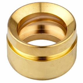
Customized brass CNC turned parts refer to high-precision brass components manufactured via CNC turning processes, tailored to specific geometric shapes, dimensional tolerances, and surface requirements of end-users. Brass—an alloy of copper (60%-75%) and zinc (25%-40%)—exhibits inherent advantages for CNC turning: excellent machinability (cutting speed up to 300 m/min), good corrosion resistance (superior to carbon steel), and favorable ductility (enabling complex forming like thin-walled structures).
Unlike standardized off-the-shelf parts, customized brass turned parts cover diverse geometries: from micro-scale electronic pins (φ0.5-2 mm) to large industrial valves (φ50-200 mm), and from simple cylindrical shafts to complex components with eccentric holes, multi-start threads, or irregular grooves. They are widely used in industries such as:
- Electronics: Brass connector pins (tolerance ±0.005 mm) for connectors;
- Plumbing & Sanitary: Custom brass valve cores (surface roughness Ra ≤ 0.4 μm) for faucets;
- Aerospace: Precision brass sensor housings (concentricity ≤ 0.003 mm);
- Watchmaking: Micro brass gear shafts (length-diameter ratio 10:1) for mechanical watches.
1. Technical Essence of Customized Brass CNC Turning
(1) Material Characteristics of Brass and Machining Adaptation
The machining performance of customized brass parts is directly determined by brass alloy grades, with the two most common grades for turning being:
|
Brass Grade
|
Composition (Cu/Zn)
|
Machinability Rating (1=poor, 10=excellent)
|
Key Machining Features
|
|
H62
|
62%/38%
|
8
|
Balanced strength (σb=300 MPa) and ductility; suitable for medium-load parts (e.g., valve stems).
|
|
H65
|
65%/35%
|
9
|
Higher copper content, better surface finish (Ra ≤ 0.4 μm); ideal for precision parts (e.g., watch gears).
|
Critical material-induced machining considerations:
- Chip Control: Brass produces continuous curly chips during turning; customized chip breaker grooves (e.g., “U-type” for H62) are required to avoid chip entanglement with the tool or workpiece.
- Stickiness Prevention: Brass has moderate adhesion (lower than aluminum but higher than steel); high-speed cutting (V ≥ 200 m/min) or TiN-coated tools reduce built-up edge (BUE) formation.
- Thermal Deformation: Brass has a low thermal expansion coefficient (19×10⁻⁶/°C, 50% lower than aluminum); however, thin-walled parts (thickness ≤ 1 mm) still require cooling to avoid thermal warpage (temperature ≤ 150°C).
(2) Customization-Driven Geometric Challenges
Customized brass parts often feature complex geometries that exceed standard turning capabilities, posing three core technical challenges:
- Micro-Structure Machining: For micro-parts (e.g., φ0.8 mm electronic pins), tool diameter (≤ 0.5 mm) and spindle runout (≤ 0.001 mm) become critical to avoid tool breakage.
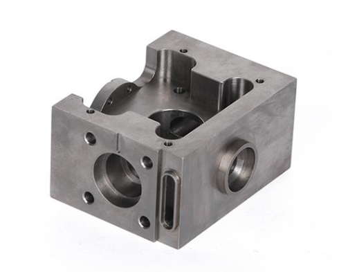
- Multi-Feature Integration: Parts with combined features (e.g., a brass shaft with a φ5 mm eccentric hole + M8×1 thread + 0.5 mm deep annular groove) require precise coordination of tool changes and axis movements.
- Irregular Contours: Non-circular profiles (e.g., hexagonal brass knobs) demand synchronized control of X/Z axes (via NURBS interpolation) to ensure contour accuracy (error ≤ ±0.005 mm).
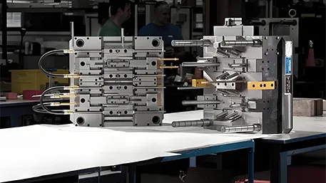
2. Hardware System Architecture for Customized Brass CNC Turning
(1) Key Hardware Modules and Brass-Adapted Specifications
|
Hardware Module
|
Technical Requirements (Brass-Specific)
|
Technical Role
|
|
Cutting Tools
|
– Material: High-Speed Steel (HSS-E, for low-speed fine turning) or TiN-coated Carbide (WC-Co, for high-speed roughing).- Geometry: Front angle γₒ=12°-15° (reduces cutting force), nose radius rₑ=0.1-0.3 mm (for micro-parts).
|
Ensure smooth cutting of brass; minimize BUE and tool wear.
|
|
Spindle Unit
|
– Speed range: 3000-12000 rpm (H65 brass: 8000-12000 rpm for fine turning; H62 brass: 3000-6000 rpm for roughing).- Runout: Radial runout ≤ 0.001 mm (critical for micro-pin machining).
|
Provide stable high-speed rotation; avoid dimensional errors from spindle vibration.
|
|
Custom Fixtures
|
– Type: Collet chucks (for cylindrical parts, clamping accuracy ±0.002 mm) or jaw chucks with custom soft jaws (for irregular parts, e.g., hexagonal brass nuts).- Clamping force: 50-500 N (adjustable to prevent deformation of thin-walled brass parts).
|
Secure workpiece positioning; match the unique shape of customized parts.
|
|
Cooling System
|
– Coolant type: Emulsion (concentration 5%-8%, avoids brass oxidation) or synthetic coolant (for high-speed turning, thermal conductivity ≥ 0.5 W/m·K).- Flow rate: 5-15 L/min (directed at cutting zone via 0.5-1 mm diameter nozzles).
|
Reduce cutting temperature; flush chips; prevent brass surface discoloration.
|
|
Tool Turret
|
– Station count: 8-12 stations (accommodates diverse tools: turning tools, threading tools, boring tools for customized features).- Tool change time: ≤ 0.8 s (tool-to-tool, minimizes downtime for multi-feature parts).
|
Support quick tool switching for complex customized geometries.
|
(2) Customization-Enhanced Hardware Upgrades
- Micro-Tool Adaptation: For parts with micro-holes (φ0.3-1 mm), the CNC lathe is equipped with a high-precision micro-boring unit (coaxiality ≤ 0.002 mm) and a tool length sensor (resolution 0.1 μm) to avoid tool overcutting.
- Irregular Workpiece Clamping: For non-circular customized parts (e.g., brass camshafts), a “profile-matching fixture” is used—machined to the exact reverse shape of the workpiece’s base, ensuring clamping contact area ≥ 80% and reducing deformation.
3. Core Control Algorithms for Customized Brass CNC Turning
(1) Complex Path Planning for Custom Geometries
- NURBS Interpolation for Irregular Contours:
For customized brass parts with free-form surfaces (e.g., brass decorative knobs with curved profiles), the CNC system uses 3rd-order NURBS interpolation to fit the design curve. The interpolation error is controlled within 0.001 mm, and the calculation frequency (≥ 1000 Hz) ensures smooth tool movement—avoiding surface scratches caused by abrupt path changes.
- Multi-Feature Process Sequencing:
For parts with combined features (e.g., “shaft + thread + hole”), the system optimizes the machining sequence via a priority algorithm:
-
- Rough turning (remove 80% of material, V=250 m/min, f=0.2 mm/r);
-
- Boring (machining the hole, V=200 m/min, f=0.1 mm/r);
-
- Thread turning (M8×1, spindle synchronization accuracy ±0.1°);
-
- Fine turning (final dimension, V=300 m/min, f=0.05 mm/r).
This sequence minimizes tool retractions and ensures dimensional consistency between features.
(2) Brass-Specific Error Compensation
- Thermal Deformation Compensation:
Brass parts (especially thin-walled ones, thickness 0.5-1 mm) expand by 0.003-0.005 mm when heated to 150°C. The system uses a temperature-feedforward model:
-
- Measure cutting zone temperature via a thermocouple (resolution 1°C);
-
- Calculate expansion amount (ΔL = α×L×ΔT, α=19×10⁻⁶/°C);
-
- Adjust the Z-axis position in real time to offset expansion, ensuring length tolerance ≤ ±0.003 mm.
- Tool Wear Compensation:
Brass turning causes gradual tool wear (flank wear VB=0.1 mm after 30 minutes of machining). The system implements force-based wear monitoring:
-
- Measure cutting force via a piezoelectric sensor (resolution 0.1 N);
-
- When force increases by 20% (indicating VB=0.2 mm), automatically adjust the tool radius compensation value (Δr=0.002 mm) to maintain dimensional accuracy.
4. Precision Detection and Calibration Technology
(1) Customized Dimension and Surface Detection
- Dimensional Accuracy Detection:
-
- For micro-parts (e.g., φ1 mm pins): Use a toolmaker’s microscope (magnification 50×, accuracy ±0.0005 mm) to measure diameter and concentricity.
-
- For large parts (e.g., φ100 mm valves): Use a coordinate measuring machine (CMM, accuracy ±0.001 mm) to inspect all customized features (holes, threads, grooves) in one setup.
- Surface Quality Detection:
-
- Surface roughness: Use a contact-type roughness tester (Ra resolution 0.001 μm) to sample 3 points on the workpiece (avoiding edges) — ensure Ra ≤ 0.4 μm for decorative brass parts.
-
- Surface defects: Use a vision inspection system (200× magnification) to detect micro-scratches (depth ≤ 0.001 mm) or oxidation spots (common in brass if coolant is contaminated).
(2) Machine and Tool Calibration
- Spindle Speed Calibration:
Brass turning requires precise speed control (e.g., 8000 rpm for H65 fine turning). Use a laser tachometer to verify speed—deviation must be ≤ ±1%. If exceeded, adjust the spindle inverter’s frequency gain (e.g., from 1.0 to 1.02) to correct.
- Tool Offset Calibration:
After installing a new tool (e.g., a threading tool for M5×0.8 threads), use a tool setter (accuracy ±0.0005 mm) to measure:
-
- Tool length offset (Z-axis): Ensure thread depth error ≤ 0.01 mm.
-
- Tool radius offset (X-axis): Compensate for tool tip wear (critical for thread profile accuracy).
5. Typical Process Difficulties and Technical Breakthroughs
(1) Micro-Thin-Walled Brass Part Deformation (Thickness ≤ 0.8 mm)
Challenge: Clamping force (≥ 100 N) causes ovality error > 0.01 mm; cutting force (≥ 50 N) leads to wall warpage.
Solutions:
- Flexible Clamping: Use a pneumatic collet chuck with a polyurethane sleeve (Shore hardness 60A) to distribute clamping force—reduce local pressure to ≤ 0.5 MPa, ovality error ≤ 0.005 mm.
- Light-Cutting Strategy: Adopt high speed (V=300 m/min) and low feed rate (f=0.03 mm/r), depth of cut aₚ=0.05 mm (multi-pass: 4-6 passes) to minimize cutting force (< 30 N).
(2) Customized Brass Thread Machining (e.g., M3×0.5 Fine Thread)
Challenge: Brass’s ductility causes thread burrs (height > 0.01 mm); thread pitch error > 0.005 mm due to spindle synchronization lag.
Solutions:
- Burr Prevention: Use a “negative rake angle threading tool” (γₒ=-5°) to shear chips instead of tearing brass; after threading, perform a 0.1 mm deep “light cut” on the thread crest to remove burrs.
- Synchronization Optimization: Increase the spindle encoder resolution (from 20 bits to 24 bits) to improve angle control accuracy (±0.05°); use “thread pitch compensation” to correct cumulative pitch error (reduce to ≤ 0.003 mm).
(3) Brass Oxidation and Corrosion (Critical for Plumbing Parts)
Challenge: Cutting coolant contamination or air exposure causes brass to develop a green oxide layer (tarnish) within 24 hours.
Solutions:
- Coolant Management: Use a coolant filtration system (5 μm filter) to remove metal chips; add a corrosion inhibitor (0.5% concentration) to the emulsion to extend anti-oxidation time to 72 hours.
- Post-Machining Treatment: Immediately after turning, clean the workpiece with ethanol (to remove coolant residue) and apply a thin layer of anti-tarnish oil (thickness 5-10 μm) to prevent oxidation.
6. Common Issues and Troubleshooting
(1) Workpiece Surface Scratches
Causes:
- Curly brass chips scratch the machined surface (common if chip breaker is mismatched).
- Coolant flow is insufficient (nozzle blocked, flow rate < 5 L/min), leading to chip accumulation.
Troubleshooting:
- Replace the chip breaker with a “narrow-groove type” (suitable for brass) to produce short C-shaped chips.
- Clean the coolant nozzle (use a 0.5 mm drill bit to clear blockages) and increase flow rate to 8-10 L/min.
(2) Dimensional Overrun (e.g., Diameter Too Small by 0.008 mm)
Causes:
- Tool wear exceeds the compensation threshold (VB=0.3 mm, uncompensated).
- Thermal expansion of the workpiece is underestimated (cutting zone temperature reaches 180°C, ΔL=0.006 mm).
Troubleshooting:
- Replace the worn tool and reset the tool radius compensation value (add 0.003 mm to the original offset).
- Increase coolant flow rate to 15 L/min to reduce cutting zone temperature to ≤ 120°C; adjust the thermal compensation coefficient from 19×10⁻⁶/°C to 20×10⁻⁶/°C (for higher accuracy).
Conclusion: The Future of Customized Brass CNC Turned Parts
Customized brass CNC turned parts are evolving toward “higher precision + more complex customization + greener processes”:
- Micro-Precision Development: For electronic and watchmaking industries, micro-brass parts with dimensions ≤ 0.5 mm (e.g., φ0.3 mm sensor pins) will require ultra-high-precision CNC lathes (spindle runout ≤ 0.0005 mm) and nanoscale tooling.
- Multi-Material Integration: Customized brass parts will combine with other materials (e.g., brass-aluminum bimetallic shafts) via hybrid CNC processes (turning + laser welding), expanding application scenarios in automotive electronics.
- Green Machining: Dry or minimum quantity lubrication (MQL) systems will replace traditional coolants—MQL uses 5-10 mL/h of vegetable oil (vs. 10 L/min of emulsion), reducing waste and avoiding brass oxidation from coolant contamination.
For manufacturers, mastering brass’s material 特性 (machinability, oxidation) and custom geometry 适配 (micro-structures, multi-features) is key to delivering high-quality parts. As industries like 5G electronics and smart plumbing demand more precise, diverse customized components, the synergy between CNC technology and brass processing will continue to drive innovation in this field.