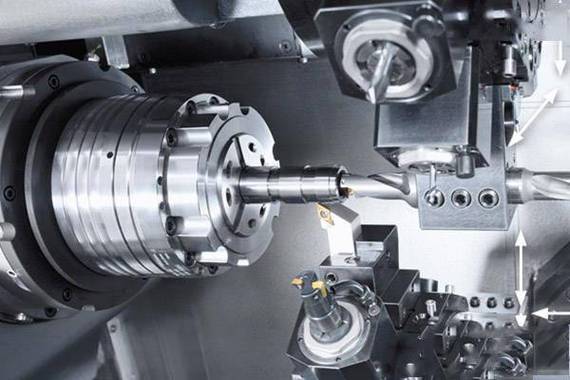
Insert CNC turning refers to a high-precision machining process that combines replaceable cutting inserts (the core cutting component) with CNC lathes to achieve efficient turning of metal workpieces. Unlike traditional integral tools (e.g., solid carbide turning tools), cutting inserts feature standardized geometric designs and quick-change structures—they can be replaced within 1-2 minutes after wear, significantly reducing tool change time and improving production efficiency.
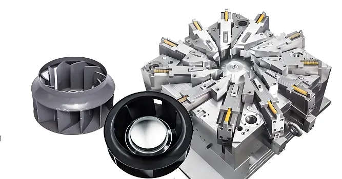
The core advantage of this technology lies in the “synergy between insert performance and CNC control”: the CNC system precisely adjusts cutting parameters (speed, feed rate, depth of cut) based on the insert’s material properties (e.g., carbide, ceramic, CBN) and workpiece material (e.g., steel, aluminum, titanium alloy), while the insert’s specialized groove design (chip breaker) and coating (e.g., TiAlN, AlCrN) ensure stable chip removal and long tool life. It is widely used in automotive powertrain parts (crankshafts, camshafts), hydraulic components (valve cores), and precision mechanical parts manufacturing.
1. Technical Essence and Geometric Design of Cutting Inserts
(1) Core Geometric Parameters of Inserts
The cutting performance of inserts is directly determined by their geometric parameters, which must be matched with the CNC turning process requirements (e.g., workpiece shape, surface roughness).
|
Geometric Parameter
|
Definition
|
Impact on Machining Performance
|
|
Nose Radius (rₑ)
|
Radius of the arc connecting the main cutting edge and secondary cutting edge
|
– Small rₑ (0.2-0.4 mm): Suitable for fine turning (Ra ≤ 0.8 μm), reduces cutting forces but increases tool wear.- Large rₑ (1.2-2.0 mm): Suitable for rough turning, improves tool rigidity but may cause vibration in thin-walled parts.
|
|
Lead Angle (κᵣ)
|
Angle between the main cutting edge and the workpiece axis
|
– κᵣ=90°: Suitable for end-face turning, minimizes radial cutting force.- κᵣ=45°-75°: Suitable for external turning, balances radial and axial forces.
|
|
Clearance Angle (αₒ)
|
Angle between the flank face and the workpiece’s machined surface
|
Typically 5°-12°; too small causes flank wear, too large reduces tool rigidity.
|
|
Chip Breaker Groove
|
Special groove on the insert’s rake face
|
Controls chip shape (e.g., C-type, spiral chips) to avoid chip entanglement with the workpiece or tool.
|
(2) Insert Standardization and Interface Matching
Inserts follow international standards (ISO 1832) for 型号 coding (e.g., CNMG120408):
- C: Insert shape (diamond, 80° included angle);
- N: Relief angle (0°);
- M: Tolerance class (medium, ±0.05 mm for insert thickness);
- G: Hole type (with through hole for clamping);
- 12: Insert width (12.7 mm);
- 04: Insert thickness (4.76 mm);
- 08: Nose radius (0.8 mm).
The insert must match the tool holder’s interface precisely:
- Mechanical clamping: Screw clamping (for through-hole inserts) or lever clamping (for solid inserts) ensures clamping force of 5-8 N·m, controlling insert radial runout ≤ 0.01 mm.
- Tool holder interface: Common standards include CAPTO (for high rigidity, used in heavy-duty turning) and VDI (for quick change, used in automotive mass production), with coaxiality error ≤ 0.005 mm between tool holder and spindle.
2. Hardware System Architecture for Insert CNC Turning
(1) Key Hardware Modules and Technical Specifications
|
Hardware Module
|
Technical Requirements
|
Technical Role
|
|
Cutting Insert
|
– Material: Carbide (WC-Co, for general steel); Ceramic (Al₂O₃, for high-speed turning of cast iron); CBN (for hardened steel, HRC ≥ 55).- Coating: TiAlN (max service temp 800°C); AlCrN (max service temp 1100°C).
|
Provide cutting edge; coating reduces friction and wear.
|
|
Tool Holder
|
– Rigidity: Bending stiffness ≥ 200 N/μm.- Cooling: Internal coolant channel (flow rate ≥ 15 L/min, pressure ≥ 5 MPa) for chip evacuation.
|
Clamp insert; deliver coolant to cutting zone; absorb cutting vibration.
|
|
Spindle Unit
|
– Speed range: 50-8000 rpm (for carbide inserts); 1000-15000 rpm (for ceramic inserts).- Dynamic balance: G0.4 (to avoid insert chipping from vibration).
|
Provide rotational power; ensure stable cutting speed.
|
|
Servo Feed System
|
– Positioning accuracy: ±0.001 mm.- Feed rate range: 0.01-2000 mm/min (adjustable based on insert wear status).
|
Drive tool movement; match feed rate with insert cutting performance.
|
|
Tool Condition Monitoring (TCM)
|
– Sensors: Piezoelectric force sensors (measure cutting force, resolution 0.1 N); Thermocouples (monitor cutting zone temp, resolution 1°C).
|
Real-time detect insert wear (wear threshold: 0.3 mm for flank wear) or breakage.
|
(2) Insert Cooling and Chip Evacuation Design
- High-pressure coolant system: Delivers coolant (emulsion or oil) to the cutting edge via a tool holder’s internal channel, with a nozzle positioned 1-2 mm from the insert’s rake face. This reduces cutting zone temperature by 30%-50% (from 800°C to 400-560°C) and prevents chip adhesion to the insert (critical for machining stainless steel, e.g., 304).
- Chip breaker optimization: For ductile materials (e.g., aluminum alloy), use inserts with “wide groove + shallow rake angle” chip breakers to produce short spiral chips; for brittle materials (e.g., cast iron), use “narrow groove + steep rake angle” designs to avoid powdery chip accumulation.
3. Core Control Algorithms for Insert CNC Turning
(1) Tool Path and Cutting Parameter Optimization
- Tool nose radius compensation (G41/G42):
Since inserts have a nose radius (rₑ), the CNC system automatically calculates the offset distance (equal to rₑ) between the tool center and the workpiece contour. This eliminates dimensional errors caused by the nose radius—for example, when turning a cylindrical surface with rₑ=0.8 mm, the compensation ensures the workpiece diameter error ≤ ±0.002 mm.
- Adaptive cutting parameter adjustment:
The CNC system uses TCM sensor data to dynamically optimize parameters:
-
- When insert flank wear reaches 0.2 mm (50% of the threshold), reduce feed rate by 10%-15% to extend tool life.
-
- For workpiece material hardness variations (e.g., 45# steel with hardness 180-220 HB), adjust cutting speed: 180 HB → 250 m/min; 220 HB → 220 m/min (to maintain stable cutting force ≤ 3 kN).
(2) Insert Life Prediction and Management
- Empirical life model:
Based on the Taylor tool life equation: VTⁿ = C (V=cutting speed, T=tool life, n=material constant, C=insert constant). For example:
-
- Carbide insert (WC-Co) machining 45# steel: n=0.25, C=600 → V=200 m/min → T=120 min; V=250 m/min → T=65 min.
- AI-based life prediction:
Integrate historical machining data (10,000+ cycles) into a neural network model, which considers insert type, workpiece material, and cutting force to predict life with an accuracy of ≥ 90%. When the predicted life is < 10 min, the system sends a “replace insert” alert.
4. Precision Detection and Calibration Technology
(1) Insert Installation Precision Calibration
- Pre-setting with tool presetter:
Use a tool presetter (e.g., Zoller V3) to measure:
-
- Radial runout of the insert cutting edge: ≤ 0.005 mm.
-
- Axial (end) runout: ≤ 0.003 mm.
Input the measured data into the CNC system to compensate for tool length and radius offsets.
- On-machine verification:
After installing the tool holder, use a touch probe (e.g., Renishaw MP250) to test-cut a small section of the workpiece, then measure the machined diameter and surface roughness (Ra). If Ra > 1.6 μm, recheck the insert’s clamping status (e.g., loose screws) or replace the insert.
(2) Spindle and Feed Axis Calibration for Insert Cutting
- Spindle speed accuracy calibration:
Use a tachometer to measure spindle speed at 1000, 3000, 5000 rpm—speed deviation must be ≤ ±2%. If deviation exceeds 5%, adjust the spindle inverter parameters (e.g., frequency gain).
- Feed axis backlash compensation:
Use a laser interferometer to measure backlash of X/Z axes (≤ 0.001 mm). Input compensation values into the CNC system to avoid “tool hesitation” during direction changes (which causes surface scratches on the workpiece).
5. Typical Process Difficulties and Technical Breakthroughs
(1) Machining of Sticky Materials (e.g., 304 Stainless Steel)
Challenge: Chips adhere to the insert’s rake face, causing built-up edge (BUE) and surface roughness degradation (Ra > 3.2 μm).
Solutions:
- Select inserts with TiAlN-AlCrN composite coating (reduces friction coefficient to 0.2).
- Use high-pressure coolant (10 MPa) to flush chips away from the cutting edge.
- Optimize cutting parameters: V=120-150 m/min, f=0.1-0.15 mm/r (avoids low speed-induced BUE).
(2) High-speed Turning of Thin-walled Workpieces (e.g., Aluminum Alloy Cylinders, Wall Thickness 0.5-1 mm)
Challenge: Cutting force causes workpiece deformation (ovality error > 0.02 mm); insert vibration leads to chipping.
Solutions:
- Use inserts with small nose radius (rₑ=0.2 mm) and sharp cutting edge (rake angle γₒ=15°) to reduce radial cutting force (≤ 500 N).
- Adopt a “light-cutting” strategy: depth of cut aₚ=0.1-0.2 mm, multi-pass machining (3-4 passes) instead of single-pass heavy cutting.
- Mount the workpiece on a hydraulic chuck with soft jaws (hardness HRC20) to distribute clamping force evenly.
(3) Turning of Hardened Steel (e.g., 40Cr, HRC 50-55)
Challenge: High cutting temperature (≥ 1000°C) causes rapid insert wear (life < 20 min).
Solutions:
- Use CBN (cubic boron nitride) inserts (thermal conductivity 130 W/m·K, 3x higher than carbide).
- Implement dry cutting (avoid coolant-induced thermal shock to CBN inserts) with V=80-120 m/min, f=0.08-0.1 mm/r.
- Use a rigid tool holder (CAPTO C6) to minimize vibration (acceleration ≤ 0.3 g).
6. Common Issues and Troubleshooting
(1) Premature Insert Wear
Causes:
- Cutting speed too high (e.g., carbide insert machining steel at V=300 m/min, exceeding its thermal limit).
- Coolant flow insufficient (nozzle blocked, flow rate < 5 L/min).
Troubleshooting:
- Reduce cutting speed by 20%-30% (refer to the insert manufacturer’s recommended parameter table).
- Clean the coolant nozzle and check the pump pressure (ensure ≥ 5 MPa).
(2) Insert Chipping
Causes:
- Insert clamping force too low (screw torque < 5 N·m, leading to insert movement).
- Spindle dynamic balance error (G2.5 instead of G0.4, causing vibration).
Troubleshooting:
- Tighten the insert screw to the specified torque (use a torque wrench).
- Recalibrate the spindle dynamic balance (add counterweights to reduce vibration amplitude to ≤ 0.1 mm/s).
Conclusion: The Future of Insert CNC Turning
Insert CNC turning is evolving toward “intelligence + specialization”: on one hand, AI-driven TCM systems will realize real-time insert health monitoring and automatic parameter adjustment; on the other hand, customized inserts (e.g., 3D-printed ceramic inserts with porous structures for better heat dissipation) will expand applications in extreme environments (e.g., high-temperature alloy machining).
For manufacturers, mastering insert-CNC system matching technology is key to improving machining efficiency and product quality—from selecting the right insert type to optimizing cooling and calibration processes, every link directly affects the final machining results. As insert materials and CNC control technologies advance, this process will continue to set new standards for precision and efficiency in the turning industry.