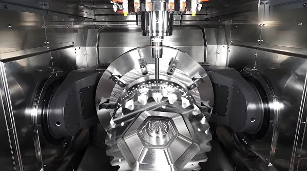
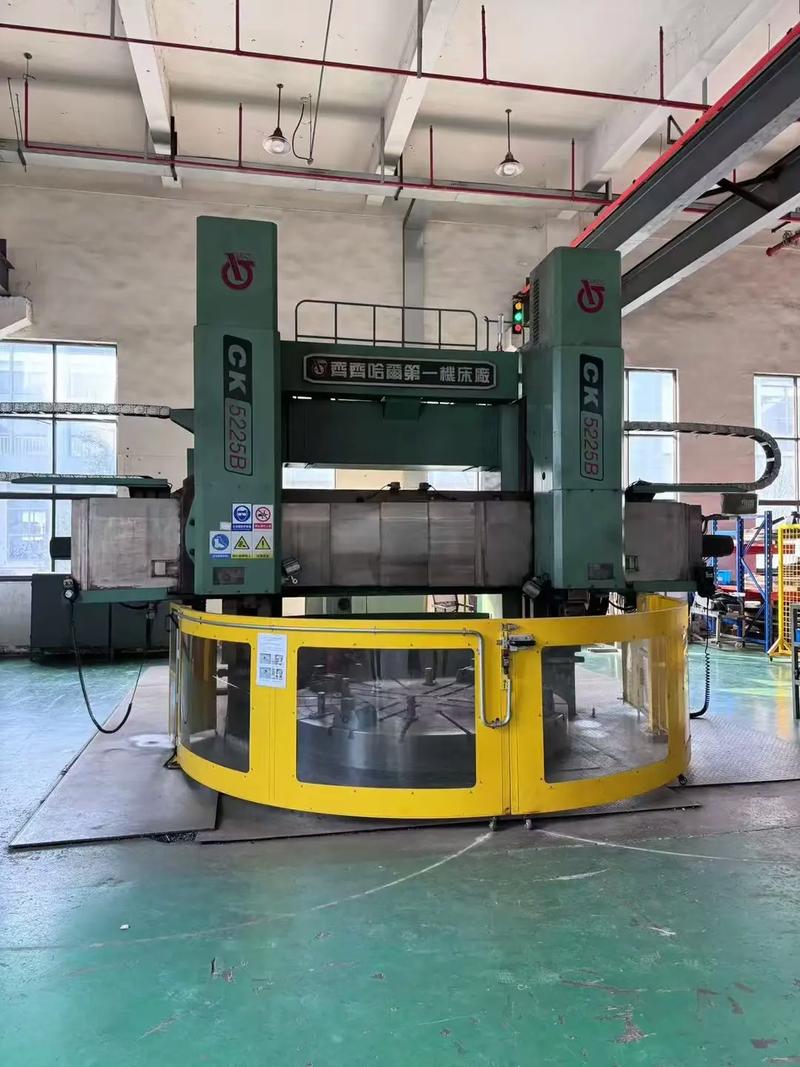
A vertical turning center (VTC) is a high-precision CNC machining equipment characterized by vertical spindle layout—the spindle axis is perpendicular to the ground, and the workpiece is clamped on a horizontal rotating table (instead of a chuck in horizontal lathes). This structural design gives VTC unique advantages in processing large-diameter, heavy-weight workpieces (e.g., flanges, wheel hubs, turbine discs) with diameters ranging from 500 mm to 5000 mm and weights up to 50 tons.
Unlike horizontal turning centers (which face challenges in workpiece loading/unloading and stability for heavy parts), VTC leverages gravity for workpiece positioning: the table’s upper surface provides stable support, reducing clamping deformation caused by workpiece weight. Additionally, its vertical layout simplifies chip evacuation (chips fall directly by gravity, avoiding accumulation on the workpiece surface) and improves space utilization (smaller floor area than horizontal lathes of the same processing capacity). It is widely used in industries such as wind power (hub machining), automotive (heavy-duty truck wheel hubs), aerospace (turbine casings), and heavy machinery (large gears).
1. Technical Essence and Structural Characteristics of VTC
(1) Core Structural Advantages of Vertical Layout
The technical uniqueness of VTC lies in its spindle-table vertical coordination mechanism, which addresses three key pain points of horizontal lathes for heavy/large workpieces:
- Workpiece stability: The horizontal table (diameter D=800-5000 mm) provides full-area support for the workpiece, with clamping force distributed evenly across the table surface. For a 10-ton flange workpiece, clamping deformation can be controlled within 0.01 mm (vs. 0.03-0.05 mm in horizontal lathes).
- Load-bearing capacity: The table is driven by a high-torque torque motor (rated torque ≥ 500 N·m) and supported by hydrostatic bearings (radial load capacity ≥ 200 kN), enabling stable rotation even with 50-ton workpieces.
- Chip evacuation efficiency: The vertical spindle orientation allows chips to fall into the chip conveyor directly (without blocking the tool path), reducing chip-induced scratches on the workpiece surface by 80% compared to horizontal lathes.
(2) Key Geometric Parameters of VTC
|
Geometric Parameter
|
Definition
|
Impact on Machining Performance
|
|
Table Diameter (D)
|
Maximum diameter of the workpiece that the table can accommodate
|
– Small D (500-1200 mm): Suitable for automotive wheel hubs (φ600-800 mm).- Large D (2000-5000 mm): Used for wind power hubs (φ3000-4000 mm) or turbine discs.
|
|
Spindle Axial Runout
|
Radial deviation of the spindle end face during rotation
|
Must be ≤ 0.002 mm; excessive runout causes end-face plane error (e.g., flange end-face flatness> 0.015 mm).
|
|
Table Rotation Accuracy
|
Radial and axial runout of the table during rotation
|
Radial runout ≤ 0.003 mm; axial runout ≤ 0.002 mm (ensures concentricity of the workpiece’s inner/outer circles).
|
|
Feed Axis Stroke (X/Z)
|
X-axis (radial) and Z-axis (axial) movement range of the tool post
|
– X-axis stroke: Typically 1/2 of the table diameter (e.g., D=2000 mm → X-stroke=1000 mm).- Z-axis stroke: 300-2000 mm (matches workpiece height, e.g., 500 mm for gear blanks).
|
2. Hardware System Architecture of VTC
(1) Key Hardware Modules and Technical Specifications
|
Hardware Module
|
Technical Requirements
|
Technical Role
|
|
Rotating Table Unit
|
– Drive: Torque motor (rated speed 50-500 rpm, peak torque ≥ 1000 N·m).- Support: Hydrostatic bearings (oil film thickness 0.02-0.05 mm, radial stiffness ≥ 50 N/μm).- Load capacity: 5-50 tons.
|
Clamp and rotate the workpiece; ensure stable operation under heavy loads.
|
|
Vertical Spindle Unit
|
– Spindle material: High-strength alloy steel (40CrNiMoA), quenched to HRC 55-60.- Bearings: Double-row cylindrical roller bearings (radial load) + angular contact ball bearings (axial load).- Speed range: 10-3000 rpm (adjustable via frequency converter).
|
Provide rotational power for cutting tools; maintain rigidity under axial cutting force.
|
|
Tool Post/Turret
|
– Type: Electric turret (12-24 tool stations) or hydraulic turret.- Tool change time: ≤ 1.5 seconds (tool-to-tool).- Repeat positioning accuracy: ±0.001 mm.
|
Store and switch cutting tools; support multi-process machining (turning, boring, threading).
|
|
Feed System (X/Z Axes)
|
– Guideway: Roller linear guideways (load capacity ≥ 50 kN, precision class H1).- Drive: Ball screws (C3 grade, lead error ≤ 0.003 mm/300 mm).- Positioning accuracy: ±0.0015 mm (X-axis); ±0.002 mm (Z-axis).
|
Drive tool movement; ensure precise tracking of the cutting path.
|
|
Hydrostatic Support System
|
– Oil supply pressure: 2-4 MPa.- Flow rate: 50-200 L/min.- Oil temperature control: ±1°C (avoids thermal deformation of the table).
|
Reduce friction between the table and base; improve rotation accuracy and load capacity.
|
(2) Specialized Design for Heavy Workpieces
- Workpiece Clamping System:
-
- Adopts “T-slot + hydraulic presser feet” (4-12 presser feet, clamping force 5-20 kN each) to distribute clamping force evenly. For 20-ton flanges, the presser feet are arranged in a circular pattern (spacing 90°) to minimize deformation.
-
- Optional vacuum clamping (for thin-walled workpieces, e.g., aluminum alloy wheel hubs) with vacuum pressure ≤ -0.08 MPa, ensuring clamping without mechanical stress.
- High-Pressure Cooling System:
-
- Equipped with a 20-30 MPa high-pressure coolant pump, delivering coolant to the cutting zone via a multi-nozzle tool holder (8-12 nozzles). This reduces cutting temperature by 40%-60% (critical for machining high-temperature alloys like Inconel 718) and flushes chips away quickly.
3. Core Control Algorithms for VTC
(1) Dynamic Balance and Gravity Compensation
- Table Dynamic Balance Control:
Heavy workpieces (e.g., 10-ton wind power hubs) often have mass imbalance, causing table vibration. The CNC system uses a two-plane dynamic balance algorithm:
-
- Measure vibration amplitude (via accelerometers, resolution 0.01 g) at 2 points on the table (upper and lower planes).
-
- Calculate the required balance weights (mass and position) and output a compensation signal to the automatic balance unit (adding/removing weights via servo motors), reducing vibration amplitude to ≤ 0.1 g.
- Z-Axis Gravity Compensation:
The Z-axis (axial feed) of VTC is vertically oriented, and the tool post’s weight (500-1000 kg) causes downward drift. The system implements feedforward gravity compensation:
-
- Precompute the required compensation force (F = mg, where m=tool post mass, g=9.8 m/s²) and input it into the servo driver.
-
- Adjust the Z-axis motor current in real time to offset gravity, ensuring positioning accuracy error ≤ 0.001 mm during static and dynamic movement.
(2) Tool Path Optimization for Large Workpieces
- Segmented Machining Algorithm:
For extra-large workpieces (e.g., φ5000 mm turbine casings), the system divides the cutting path into 5-10 segments (each segment length ≤ 500 mm) to avoid excessive feed axis load. After machining each segment, it performs a “micro-calibration” (using a touch probe to measure dimensional error) and adjusts the next segment’s path, ensuring overall dimensional accuracy ≤ ±0.005 mm.
- Adaptive Cutting Parameter Adjustment:
Based on real-time cutting force data (measured by piezoelectric sensors in the tool post, resolution 0.1 N):
-
- If cutting force exceeds 4 kN (for carbide tools machining steel), reduce feed rate by 10%-15% to prevent tool breakage.
-
- If force is too low (< 1 kN), increase cutting speed (e.g., from 150 m/min to 180 m/min) to improve efficiency, while maintaining surface roughness Ra ≤ 1.6 μm.
4. Precision Detection and Calibration Technology
(1) Table and Spindle Calibration
- Table Levelness Calibration:
Use a precision level (accuracy 0.001 mm/m) to measure the table’s levelness at 4 points (0°, 90°, 180°, 270°). The allowable deviation is ≤ 0.002 mm/m; if exceeded, adjust the hydrostatic support oil pressure (increase pressure at low points by 0.1-0.2 MPa) to correct.
- Spindle Coaxiality Calibration:
Mount a standard mandrel (φ100 mm, coaxiality ≤ 0.0005 mm) on the spindle, then use a laser interferometer to measure radial runout at 2 positions (spindle end and 300 mm from the end). The runout must be ≤ 0.002 mm; if not, adjust the spindle bearing preload (increase preload by 5%-10% for excessive runout).
(2) Feed Axis and Tool Calibration
- Feed Axis Positioning Accuracy Calibration:
Use a laser interferometer to measure X/Z axis positioning accuracy at 10 equidistant points (e.g., X-axis: 0→200→400→…→1000 mm). The maximum error must be ≤ ±0.0015 mm; input compensation values into the CNC system’s error map to eliminate deviations.
- Tool Length/Radius Calibration:
Use a tool setter (e.g., Blum TC52, accuracy ±0.0005 mm) to measure:
-
- Tool length (Z-axis offset): Ensure error ≤ 0.001 mm (critical for axial dimension accuracy, e.g., flange thickness).
-
- Tool radius (X-axis offset): Compensate for wear (e.g., after 1 hour of machining, radius may wear by 0.002 mm, requiring real-time adjustment).
5. Typical Process Difficulties and Technical Breakthroughs
(1) End-Face Flatness Control for Large Flanges (φ2000-3000 mm)
Challenge: The table’s rotation error accumulates over the large diameter, leading to end-face flatness error > 0.02 mm (exceeding the industry standard of ≤ 0.015 mm).
Solutions:
- Use a “face-milling first, turning second” process: First mill the end face with a face mill (cutting speed V=200-250 m/min) to reduce initial flatness error to ≤ 0.01 mm, then perform fine turning (V=150-180 m/min, feed rate f=0.08-0.1 mm/r) to reach Ra ≤ 0.8 μm.
- Implement real-time table runout compensation: Mount a displacement sensor (resolution 0.1 μm) near the table edge, measure runout at 100 points per revolution, and adjust the X-axis position in real time to offset deviations.
(2) Clamping Deformation of Thin-Walled Heavy Workpieces (e.g., Aluminum Alloy Wheel Hubs, Thickness 5-8 mm)
Challenge: Excessive clamping force (≥ 15 kN) causes workpiece ovality error > 0.03 mm; insufficient force leads to slippage during machining.
Solutions:
- Adopt a “flexible clamping” system: Use polyurethane presser feet (hardness Shore A 80) to increase contact area (from 20 mm² to 100 mm²), reducing local pressure to ≤ 0.15 MPa.
- Add a “pre-deformation compensation” step: Pre-measure the workpiece’s natural deformation (via a 3D scanner) and input the data into the CNC system, which adjusts the tool path to offset clamping-induced deformation (final ovality error ≤ 0.01 mm).
(3) High-Speed Turning of High-Temperature Alloys (e.g., Inconel 718 Turbine Discs)
Challenge: High cutting temperature (≥ 1200°C) causes rapid tool wear (life < 30 minutes) and surface burns.
Solutions:
- Select ceramic inserts (Al₂O₃-TiC composite, thermal conductivity 30 W/m·K) or CBN inserts (thermal conductivity 130 W/m·K) to withstand high temperatures.
- Use a 30 MPa high-pressure coolant system with a directed nozzle (1 mm from the cutting edge) to reduce temperature to 600-800°C, extending tool life to 60-90 minutes.
- Optimize cutting parameters: V=80-120 m/min, f=0.05-0.08 mm/r, depth of cut aₚ=0.5-1 mm (avoid heavy cutting to reduce heat generation).
6. Common Issues and Troubleshooting
(1) Table Vibration During Rotation
Causes:
- Workpiece mass imbalance (e.g., 10-ton hub with 5 kg imbalance).
- Hydrostatic bearing oil film thickness uneven (e.g., 0.02 mm on one side, 0.05 mm on the other).
Troubleshooting:
- Perform dynamic balance correction: Use a dynamic balance machine to measure the imbalance position and add counterweights (e.g., 5 kg at 180°) to reduce vibration amplitude to ≤ 0.1 g.
- Adjust hydrostatic oil supply: Increase oil pressure to the side with thinner film (e.g., from 2 MPa to 2.2 MPa) to balance the film thickness (0.03-0.04 mm).
(2) Z-Axis Feed Accuracy Degradation
Causes:
- Ball screw wear (lead error increases from 0.003 mm to 0.008 mm).
- Gravity compensation parameters outdated (e.g., tool post mass increased by 100 kg after tool change).
Troubleshooting:
- Replace the ball screw with a new C3-grade screw and re-calibrate positioning accuracy (ensure ≤ ±0.0015 mm).
- Recompute gravity compensation force (F = (original mass + added mass) × g) and update the servo driver parameters.
Conclusion: The Future of Vertical Turning Center
VTC is evolving toward “large-scale + intelligent + composite”:
- Large-scale development: For ultra-large workpieces in nuclear power (φ5000 mm pressure vessels) and offshore engineering (φ6000 mm flanges), VTC tables with diameters up to 8000 mm and load capacities of 100 tons will become mainstream.
- Intelligent upgrading: AI-driven monitoring systems will integrate data from vibration, force, and temperature sensors to predict tool life (accuracy ≥ 95%) and automatically adjust parameters (e.g., reducing speed when vibration exceeds 0.15 g).
- Composite machining: VTC will integrate milling, drilling, and grinding functions (e.g., vertical turn-mill centers with A/C axes) to complete multi-process machining of complex parts (e.g., wind power hubs with gear teeth) in one setup, reducing positioning errors by 50%.
For manufacturers, mastering VTC’s vertical layout-specific technologies (e.g., dynamic balance control, gravity compensation) is key to processing heavy/large precision parts. As industries like new energy (wind, nuclear) and aerospace demand larger, more complex components, VTC will remain a core equipment in high-end manufacturing, pushing the boundaries of machining scale and precision.