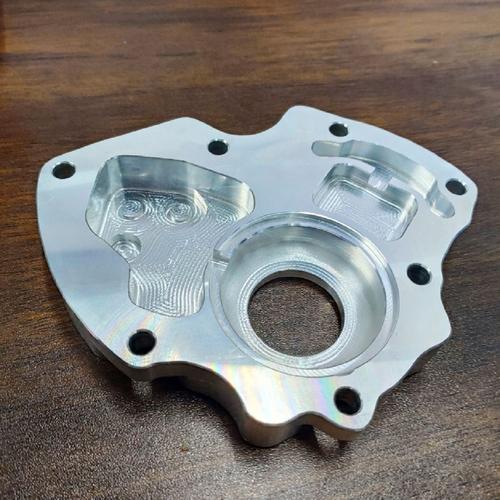
2. Core Characteristics of Custom Plain milling Parts
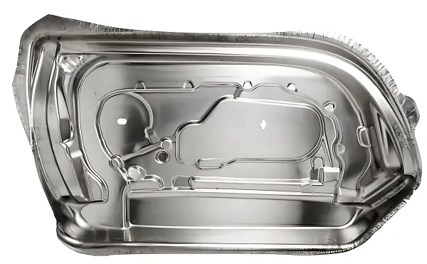
2.1 Customization-Driven Geometric Versatility
- Multi-feature planar structures: Beyond single flat surfaces, parts integrate custom features such as:
-
- Stepped planes (step height tolerance ±0.005 mm for precision assembly);
-
- Shallow open grooves (depth 0.1–5 mm, width tolerance ±0.01 mm for coolant flow or seal placement);
-
- Continuous planar contours (e.g., rectangular frames with rounded corners, radius 0.5–5 mm to avoid stress concentration).
- Dimensional flexibility: Flat surface dimensions range from 5 mm × 5 mm (micro-electronic brackets) to 2000 mm × 1500 mm (heavy machinery base plates); step count varies from 1 to 10+ (e.g., multi-stage gearbox housings).
2.2 Plain Milling-Centric Quality Requirements
- Planar geometric tolerances:
-
- Flatness: ≤0.01 mm/100 mm (aerospace parts) to ≤0.1 mm/100 mm (general industrial parts);
-
- Step perpendicularity: ≤0.005 mm/100 mm (to ensure assembly alignment);
-
- Step parallelism: ≤0.008 mm/100 mm (for load-bearing parts like engine brackets).
- Surface roughness: Ra ≤ 0.4 μm (optical or sealing surfaces), Ra ≤ 1.6 μm (mechanical assembly surfaces), Ra ≤ 3.2 μm (non-critical structural surfaces).
- Dimensional stability: Post-machining deformation (due to residual stress) controlled ≤0.003 mm for high-precision parts, achieved via stress-relief heat treatment (metals) or low-temperature annealing (plastics).
2.3 Material Diversity for Targeted Performance
|
Material Category
|
Representative Types
|
Key Performance Traits
|
Typical Plain Milling Requirements
|
|
Metals
|
Aluminum (6061-T6), Stainless Steel (316), Carbon Steel (45#)
|
High strength, rigidity, thermal conductivity
|
Tight geometric tolerances (step perpendicularity ≤0.005 mm), low surface roughness
|
|
Engineering Plastics
|
POM, ABS, PC
|
Lightweight, impact resistance, low cost
|
Minimal thermal deformation (machining temp ≤ 120°C), no burrs on step edges
|
|
Composites
|
Glass Fiber-Reinforced PP (GFRPP), Carbon Fiber-Reinforced ABS (CFRABS)
|
High strength-to-weight ratio, corrosion resistance
|
Low cutting force (to avoid fiber breakage), dust extraction systems
|
3. Core Technical Requirements for Custom Plain Milling
3.1 Material-Specific Plain Milling Parameter Optimization
|
Material
|
Tool Type
|
Cutting Speed (V)
|
Feed Rate (fₙ)
|
Depth of Cut (aₚ)
|
Key Notes
|
|
6061-T6 Aluminum
|
4-Flute Carbide End Mill
|
120–250 m/min
|
600–1200 mm/min
|
0.3–1.5 mm
|
High-speed machining reduces BUE; emulsion coolant (5–8% concentration)
|
|
316 Stainless Steel
|
6-Flute Ultra-Fine Grain Carbide End Mill
|
40–80 m/min
|
200–500 mm/min
|
0.2–0.8 mm
|
Low speed avoids work hardening; high-pressure coolant (3–5 MPa) for chip evacuation
|
|
45# Carbon Steel
|
5-Flute Carbide End Mill
|
80–150 m/min
|
400–800 mm/min
|
0.5–2 mm
|
Balanced speed/feed for rigidity; dry machining optional for roughing
|
|
POM Plastic
|
2-Flute HSS End Mill
|
60–100 m/min
|
150–300 mm/min
|
0.2–0.8 mm
|
Low feed rate prevents melting; air cooling (no liquid coolant)
|
3.2 Precision Control for Multi-Feature Planar Quality
3.2.1 Equipment Requirements
- CNC Mill Rigidity: Machine frame with reinforced cast iron (damping coefficient ≥ 0.05) to suppress chatter during step machining—critical for step perpendicularity ≤0.005 mm.
- Spindle Performance: Dynamic balance grade G0.4 (ISO 1940-1), radial runout ≤0.001 mm, and Z-axis positioning accuracy ±0.0005 mm (to control step height consistency).
- Linear Guideways: Roller-type guideways (precision class H1) with repeatability ±0.0005 mm (ensures consistent feed paths for continuous planar features).
3.2.2 Detection and Calibration
- In-Process Monitoring: Use touch probes (e.g., Renishaw MP250, accuracy ±1 μm) to measure step height and planar parallelism mid-machining—adjust Z-axis offset if deviation exceeds 30% of tolerance.
- Post-Machining Inspection:
-
- Geometric tolerances: Test with CMM (flatness accuracy ≤0.001 mm/100 mm, step perpendicularity accuracy ≤0.002 mm);
-
- Surface roughness: Measure with contact-type tester (Ra resolution 0.001 μm) at step edges and flat surfaces (3 sampling points each).
3.3 Custom Fixturing for Multi-Feature Stability
- Datum Positioning: Integrate precision locating pins (tolerance ±0.002 mm) to align the part’s base plane with the mill’s X/Y axis—ensuring step parallelism to the base ≤0.008 mm.
- Clamping Force Optimization: For stepped thin-walled parts (wall thickness ≤1.5 mm), use pneumatic clamps with rubber pads (Shore hardness 60A) to apply uniform force (30–80 N)—avoids step edge warpage.
- Modular Fixtures: For low-volume custom parts, use zero-point positioning systems (repeatability ±0.002 mm) to reduce fixture changeover time by 50% (critical for multi-variant production).
4. Classification of Custom Plain milling Parts
4.1 Automotive Industry
- Typical Parts: Engine mounting brackets (stepped planes for bolt attachment), transmission housing flanges (shallow grooves for gaskets), brake caliper support plates (multi-step planar structures).
- Technical Requirements: Step height tolerance ±0.01 mm, step perpendicularity ≤0.008 mm/100 mm, material compatibility with engine oils (e.g., 316 stainless steel, 6061-T6 aluminum).
4.2 Aerospace Industry
- Typical Parts: Aircraft wing rib brackets (continuous stepped planes), turbine engine accessory mounts (shallow grooves for wiring), satellite structure plates (precision flat surfaces with locating holes).
- Technical Requirements: Ultra-tight flatness ≤0.005 mm/100 mm, step parallelism ≤0.003 mm/100 mm, material strength (Ti-6Al-4V, CFRP) and temperature resistance (-60°C to 180°C).
4.3 Medical Device Industry
- Typical Parts: Surgical instrument frames (stepped planes for component assembly), diagnostic equipment bases (flat surfaces with shallow cable grooves), implant delivery tools (precision planar edges).
- Technical Requirements: Biocompatible materials (316L stainless steel, titanium), surface roughness Ra ≤0.4 μm (to prevent bacterial adhesion), step edge chamfers (0.1–0.2 mm radius) for safety.
4.4 Electronic Industry
- Typical Parts: PCB support brackets (stepped planes for board mounting), semiconductor equipment chamber plates (flat surfaces with shallow vacuum grooves), smartphone charger housings (small stepped features).
- Technical Requirements: Lightweight materials (6063 aluminum, ABS plastic), step height tolerance ±0.02 mm, surface coating compatibility (anodization for aluminum, electroplating for plastic).
5. Manufacturing Process of Custom Plain milling Parts
5.1 Requirements Analysis & Design
- Needs Capture: Collaborate with users to define: planar/step dimensions (length/width/step height), geometric tolerances (flatness, perpendicularity), material type, and auxiliary features (holes, chamfers).
- 3D Modeling: Use CAD software (SolidWorks, UG NX) to design features:
-
- Step transitions (avoid abrupt height changes >5 mm to reduce machining vibration);
-
- Shallow groove placement (distance ≥3 mm from part edges to prevent material weakening).
- Process Simulation: Use CAM software (Mastercam, Siemens NX CAM) to simulate plain milling paths—prioritize machining from base plane to top step (avoids re-cutting) and verify step height consistency.
5.2 Material Preparation
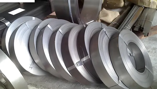
- Material Selection: Source raw materials meeting industry standards (e.g., ASTM B209 for aluminum, ASTM A240 for stainless steel) with certified mechanical properties (hardness, tensile strength).
- Blank Cutting: Cut raw material into blanks with 1–3 mm machining allowance (compensates for plain milling material removal) using sawing (metals) or CNC routing (plastics).
5.3 Fixture Installation & Part Clamping
- Fixture Setup: Mount custom fixtures on the CNC mill table, calibrate levelness (≤0.001 mm/m) and axis alignment (parallelism ≤0.001 mm/m) via laser interferometer.
- Part Clamping: Secure the blank in the fixture, use a dial indicator (accuracy ±0.001 mm) to confirm base plane alignment, and adjust clamping force to avoid deformation.
5.4 Plain Milling Execution
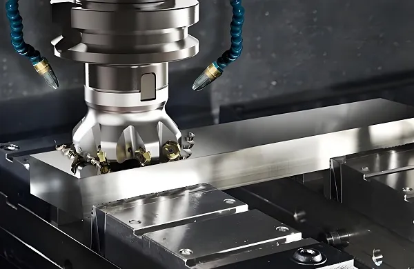
- Rough Milling: Remove 70–80% of allowance with high material removal rate parameters (e.g., 6061 aluminum: V=200 m/min, fₙ=1000 mm/min, aₚ=1.2 mm)—focus on base plane and major steps.
- Semi-Finish Milling: Reduce allowance to 0.1–0.2 mm with optimized parameters (e.g., V=220 m/min, fₙ=700 mm/min, aₚ=0.3 mm)—improve planar flatness and step definition.
- Finish Milling: Achieve final quality with tight parameters (e.g., V=250 m/min, fₙ=500 mm/min, aₚ=0.1 mm) and climb milling (reduces step edge burrs and surface scratches).
5.5 Post-Machining Treatment
- Deburring: Remove step edge burrs (height ≤0.005 mm) using CNC deburring tools (for metals) or ultrasonic cleaning (for plastics)—critical for assembly safety.
- Surface Treatment: Apply custom coatings:
-
- Anodization (aluminum parts, thickness 5–10 μm) for corrosion resistance;
-
- Passivation (stainless steel parts, 20% nitric acid solution) for rust prevention;
-
- Powder coating (steel parts, thickness 60–80 μm) for impact resistance.
- Stress Relief: For metal parts, perform annealing (aluminum: 350°C/1h; steel: 650°C/2h) to eliminate residual stress—ensures dimensional stability in service.
5.6 Quality Inspection & Delivery
- Comprehensive Testing: Inspect all custom requirements: geometric tolerances (CMM), surface roughness (tester), dimensional accuracy (calipers/micrometers), and material compliance (spectroscopy).
- Documentation: Provide a “certificate of conformance” with test data, material certification, and process records (required for aerospace/medical industries).
6. Quality Control and Common Challenges
6.1 Key Quality Control Measures
- Process Stability Monitoring: Track spindle vibration (accelerometer, resolution 0.01 mm/s) and cutting force (piezoelectric sensor, resolution 0.1 N)—halt machining if vibration >0.1 mm/s (causes step deviation) or force >4 kN (metals).
- Statistical Process Control (SPC): Collect data from 30+ parts to calculate process capability (Cₚ ≥ 1.33 for step height, Cₚ ≥ 1.67 for flatness)—identify deviations early.
- Environmental Control: Maintain workshop temperature (20±2°C) and humidity (40–60%)—avoids thermal deformation of parts (critical for step height tolerance ±0.01 mm).
6.2 Common Challenges and Solutions
|
Challenge
|
Root Cause
|
Solution
|
|
Step Height Deviation (>±0.01 mm)
|
Z-axis positioning error (>0.0005 mm); tool wear (flank wear VB >0.3 mm)
|
Recalibrate Z-axis with laser interferometer; replace tool and reset offset.
|
|
Step Perpendicularity Error (>0.008 mm/100 mm)
|
Fixture misalignment (>0.001 mm/m); spindle runout (>0.001 mm)
|
Re-level fixture; adjust spindle bearings to reduce runout.
|
|
Surface Scratches (Ra >1.6 μm)
|
Chip re-cutting; coolant contamination
|
Increase coolant pressure to 4 MPa; filter coolant (5 μm mesh) to remove debris.
|
|
Part Deformation (Thin-Walled Stepped Parts)
|
Clamping force too high (>80 N); cutting heat (>180°C)
|
Reduce force to 30–50 N; use cryogenic cooling (liquid nitrogen) for metals.
|
7. Development Trends of Custom Plain milling Parts
7.1 Intelligent Machining
- AI-Driven Parameter Optimization: Machine learning models (trained on 10,000+ cycles) auto-select plain milling parameters for multi-feature parts—reduces setup time by 50% and step height deviation by 30%.
- Digital Twins: Virtual replicas of the process (integrating part design, machine status, and environmental data) predict defects (e.g., step chatter) before production—lowers scrappage by 40%.
7.2 Material Innovation
- Advanced Composites: Wider adoption of CFRP and metal matrix composites (MMCs) for lightweight parts—requires diamond-coated end mills (wear resistance 5× carbide) and low-force machining (≤2 kN).
- Bio-Based Plastics: Use of PLA and PHA for eco-friendly parts—demands low-temperature plain milling (≤100°C) to avoid material degradation.
7.3 Green Manufacturing
- Minimum Quantity Lubrication (MQL): Replace coolant with 5–10 mL/h vegetable oil-based lubricant—reduces waste by 99% and avoids environmental pollution.
- Energy-Efficient Equipment: Use CNC mills with regenerative spindle drives (recover 15% energy during deceleration) and LED lighting—lowers carbon footprint by 25%.

