Preface
Micro Injection Molding is a precision molding technology developed for “miniaturized, high-precision, and highly complex” plastic parts. It enables the manufacturing of parts with weights ranging from milligram-level (0.1mg) to sizes from micrometer-level (10μm) to millimeter-level. Widely used in fields such as minimally invasive medical devices, microelectronic components, and automotive precision sensors, this manual systematically organizes the core technical points, process control difficulties, and practical application solutions of micro injection molding. It helps practitioners master the full-process key technologies from equipment selection to finished product quality control, and solve common problems in micro injection molding production.
Ⅰ. Basic Understanding of Micro Injection Molding
1.1 Definition and Core Characteristics
- Definition: Micro Injection Molding is a molding process that uses high-precision injection equipment to inject molten plastic into micro mold cavities at high pressure and high speed, followed by pressure holding and cooling to form parts with microstructures (such as microchannels, micro bosses, micro holes) or overall miniaturized parts. It typically meets any of the following criteria:
-
- Part weight ≤ 1g (typically 0.1-500mg);
-
- Critical dimension ≤ 1mm (e.g., hole diameter ≤ 0.1mm, wall thickness ≤ 0.05mm);
-
- Surface with micrometer-level structures (e.g., 1-100μm patterns, arrays).
- Core Characteristics:
▶ High Precision: Dimensional tolerance can reach ±0.001mm, and form and position tolerance (e.g., coaxiality, flatness) ≤ 0.005mm;
▶ High Material Utilization: Small single injection volume (0.1-5cm³) reduces waste;
▶ High Structural Complexity: Enables integrated molding of parts with microchannels, micro gears, and multi-layer structures;
▶ High Production Efficiency: With multi-cavity molds, dozens to hundreds of parts can be produced per mold cycle.
1.2 Core Differences from Traditional Injection Molding
|
Comparison Dimension
|
Micro Injection Molding
|
Traditional Injection Molding
|
|
Part Size / Weight
|
Size ≤ 10mm, Weight ≤ 1g
|
Size ≥ 10mm, Weight ≥ 1g
|
|
Injection Volume
|
0.1-5cm³ (micro injection)
|
10-1000cm³ (large-volume injection)
|
|
Injection Speed
|
50-500mm/s (high-speed injection to avoid short shot)
|
10-100mm/s (medium-low speed)
|
|
Injection Pressure
|
150-300MPa (high pressure to overcome microcavity flow resistance)
|
50-150MPa (medium-low pressure)
|
|
Mold Precision
|
Cavity machining precision ≤ 0.001mm, Surface roughness Ra ≤ 0.1μm
|
Cavity machining precision ≤ 0.01mm, Surface roughness Ra ≤ 0.8μm
|
|
Temperature Control Precision
|
±0.1℃ (accurate temperature control to avoid material degradation / under-melting)
|
±1℃ (conventional temperature control)
|
|
Core Equipment Requirements
|
Micro-metering system, high-precision servo control
|
Large-volume metering system, stable clamping force
|
Ⅱ. Core Technical Modules of Micro Injection Molding
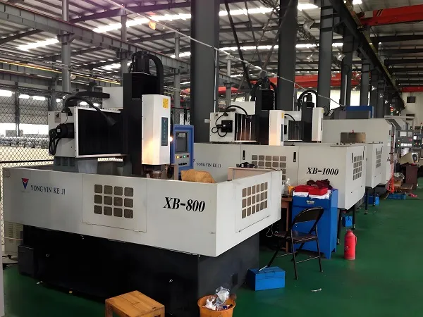
2.1 Technical Requirements for Specialized Equipment
Micro injection molding machines must meet three core requirements: “precise micro-metering, high-speed stable injection, and accurate temperature control”. The technical parameters of key components are as follows:
2.1.1 Injection System
- Metering Unit:
▶ Adopts a “micro screw + non-return valve” structure, with a screw diameter of 3-12mm (traditional injection molding machine screw diameter: 15-50mm) and metering precision ≤ ±0.1% (to ensure stable dosage during micro injection);
▶ Some equipment uses “plunger-type injection” (no screw shear), suitable for heat-sensitive high-temperature materials (e.g., PEEK, LCP).
- Injection Speed and Pressure:
▶ Maximum injection speed ≥ 200mm/s (some high-end models can reach 500mm/s), speed control precision ±0.1mm/s (to quickly fill microcavities and reduce melt cooling);
▶ Maximum injection pressure ≥ 200MPa, pressure control precision ±0.5MPa (to overcome microcavity flow resistance and ensure melt fills microstructures).
- Non-return Performance:
▶ Clearance between non-return valve and screw head ≤ 0.005mm (traditional injection molding machine ≥ 0.01mm) to prevent metering errors caused by melt backflow.
2.1.2 Clamping System
- Clamping Force:
▶ Clamping force range: 5-500kN (traditional injection molding machine ≥ 100kN). Small clamping force matches micro molds (to avoid mold deformation), with clamping force control precision ±0.1kN.
- Parallelism and Positioning Precision:
▶ Platen parallelism ≤ 0.005mm/m (to ensure cavity alignment during mold clamping and avoid flash);
▶ Tie-bar positioning precision ±0.001mm (to reduce mold offset during clamping).
2.1.3 Temperature Control System
- Barrel Temperature Control:
▶ Segmented temperature control (3-5 segments), with each segment temperature control precision ±0.1℃ (to avoid local material overheating degradation or under-melting, especially critical for high-temperature materials such as LCP and PPS);
▶ Some equipment uses “infrared heating + closed-loop temperature control” with a response time ≤ 1s (to quickly adjust temperature and adapt to material switching).
- Mold Temperature Control:
▶ Adopts “micro heating rods + temperature sensors” with sensor spacing ≤ 10mm (traditional injection molding machine ≥ 20mm), and mold cavity surface temperature control precision ±0.2℃;
▶ Supports “dynamic temperature control” (e.g., heating to material melting point + 10℃ during injection, cooling by 5℃ during pressure holding) to reduce uneven shrinkage of micro parts.
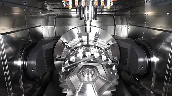
2.2 Design and Manufacturing of Micro Molds
Molds are the core of micro injection molding and must meet three requirements: “high-precision cavities, efficient venting, and easy demolding”. Key design points are as follows:
2.2.1 Cavity Design
- Precision Control:
▶ Cavity size must consider plastic shrinkage rate (shrinkage rate of micro parts is usually 10%-20% higher than traditional parts; e.g., PP micro parts: 1.5%-2.5%, traditional PP parts: 1.0%-1.5%), so pre-compensation is required during design;
▶ Cavity machining adopts a combined process of “micro-milling + EDM (Electrical Discharge Machining) + laser machining”: micro-milling for cavity body (precision ±0.002mm), EDM for microstructures (e.g., 0.05mm micro holes, precision ±0.001mm), and laser machining for surface micro-patterns (1-10μm).
- Fillets and Wall Thickness:
▶ All cavity corners must be designed with R0.01-R0.05mm fillets (traditional mold fillets: R0.1-R0.5mm) to avoid melt flow dead zones;
▶ Minimum wall thickness ≥ 0.03mm (adjusted based on material fluidity; e.g., LCP can reach 0.02mm, PP requires ≥ 0.05mm), and wall thickness variation ≤ 0.02mm (to prevent local short shot or uneven shrinkage).
2.2.2 Gate Design
- Gate Type and Size:
▶ Priority is given to “pin gates” (diameter 0.1-0.5mm) or “submarine gates” (thickness 0.05-0.2mm) to avoid gate marks affecting part precision;
▶ Gate position should be close to the farthest end of the cavity (to ensure rapid melt filling) and avoid direct alignment with microstructures (to prevent melt impact from damaging microfeatures).
- Number of Gates:
▶ Single-cavity parts usually use 1 gate (to reduce melt weld lines); multi-cavity molds (e.g., 10-100 cavities) adopt “hot runner + balanced gates” to ensure uniform filling of each cavity.
2.2.3 Venting System
- Vent Groove Design:
▶ Vent groove depth: 0.002-0.005mm (traditional mold: 0.01-0.02mm), width: 5-10mm, length covering the cavity edge (microcavities have small volume, and trapped air easily causes short shot, requiring rapid discharge);
▶ Some molds are equipped with “micro vent holes” (diameter 0.003-0.008mm) at the cavity end, combined with vacuum-assisted venting (vacuum degree -0.095MPa) to improve venting efficiency.
2.2.4 Demolding System
- Demolding Method:
▶ Uses “micro ejector pins” (diameter 0.1-0.5mm) or “ejector plates”, with clearance between ejector pins and cavity ≤ 0.002mm (to prevent flash);
▶ Thin-walled micro parts (wall thickness ≤ 0.1mm) use “pneumatic demolding” (air pressure 0.2-0.5MPa) to avoid part deformation caused by mechanical ejection.
- Mold Material:
▶ Cavity surface adopts “stainless steel (S136) + nitriding treatment” (hardness HV ≥ 800) or “tungsten carbide alloy” (hardness HV ≥ 1500) to ensure wear resistance (micro mold cavities are small and difficult to repair after wear).
2.3 Material Selection and Pretreatment
Micro injection molding materials must meet the requirements of “high fluidity, low shrinkage rate, and high stability”. Material selection for different application scenarios is as follows:
2.3.1 Common Materials and Their Properties
|
Material Type
|
Representative Material
|
Melting Point / Molding Temperature
|
Fluidity (MFR)
|
Shrinkage Rate
|
Typical Application Fields
|
|
High-Temperature Engineering Plastics
|
LCP (Liquid Crystal Polymer)
|
280-340℃
|
50-100g/10min
|
0.2%-0.8%
|
Micro connectors, sensors
|
|
PEEK (Polyether Ether Ketone)
|
340-390℃
|
10-30g/10min
|
1.0%-1.5%
|
Minimally invasive medical devices
|
|
|
General Engineering Plastics
|
PA66 + Glass Fiber
|
250-280℃
|
20-50g/10min
|
0.8%-1.2%
|
Micro gears, automotive sensors
|
|
PC (Polycarbonate)
|
260-300℃
|
10-30g/10min
|
0.5%-0.8%
|
Optical micro parts
|
|
|
Medical-Grade Plastics
|
Medical-Grade PP
|
180-220℃
|
30-60g/10min
|
1.2%-1.8%
|
Medical catheter accessories
|
|
PPSU (Polyphenylsulfone)
|
300-340℃
|
15-30g/10min
|
0.6%-1.0%
|
Blood-contacting parts
|
2.3.2 Material Pretreatment Requirements
- Drying Treatment:
▶ Hygroscopic materials (e.g., PA66, PC) need to be dried at 80-120℃ for 2-4 hours, with moisture content ≤ 0.02% (micro injection volume is small, and trace moisture causes melt degradation and bubbles);
▶ High-temperature materials (e.g., PEEK, LCP) require drying at 120-150℃ for 4-6 hours to avoid surface defects of parts caused by insufficient drying.
- Material Particle Size:
▶ Uses granular materials with particle size 0.1-0.5mm (traditional injection molding material particle size: 0.5-2mm) to ensure uniform feeding into the barrel and reduce metering errors.
2.4 Control of Key Process Parameters
Process parameters of micro injection molding significantly affect part quality. The following core parameters need precise control:
2.4.1 Injection Stage Parameters
- Injection Speed:
▶ Recommended value: 50-300mm/s, adjusted based on material fluidity: high-fluidity materials (e.g., LCP) use 100-200mm/s, low-fluidity materials (e.g., PEEK) use 200-300mm/s (rapid filling to avoid premature melt cooling in microcavities);
▶ Avoid excessively high speed (>300mm/s) to prevent melt shear overheating degradation or flash.
- Injection Pressure:
▶ Recommended value: 150-250MPa, ensuring “filling pressure > microcavity flow resistance” (flow resistance of microcavities is 5-10 times that of traditional cavities);
▶ Adopts “segmented pressure control”: low pressure (150-180MPa) in the early filling stage to avoid impacting microstructures, and high pressure (200-250MPa) in the late filling stage to ensure full filling.
2.4.2 Holding Pressure Stage Parameters
- Holding Pressure and Time:
▶ Holding pressure is 60%-80% of injection pressure (e.g., injection pressure 200MPa, holding pressure 120-160MPa) to avoid mold deformation caused by excessive pressure;
▶ Holding time: 0.5-2s (traditional injection molding: 3-10s). Micro parts cool quickly, and excessively long holding time easily increases internal stress of parts.
- Holding Pressure Switching Timing:
▶ Adopts “position switching” (switching to holding pressure when filling 95%-98% of the cavity) to avoid short shot or over-holding pressure caused by “time switching”.
2.4.3 Cooling Stage Parameters
- Cooling Temperature:
▶ Mold cooling temperature is 10-20℃ lower than the material’s glass transition temperature (e.g., PC glass transition temperature 150℃, cooling temperature 130-140℃) to reduce uneven shrinkage of parts;
▶ Micro parts have thin walls (≤0.1mm) and short cooling time (1-3s) to avoid part sticking to the mold due to excessively long cooling.
- Cooling Method:
▶ Uses “micro cooling channels” (diameter 1-3mm, traditional cooling channels: 5-10mm), with channels 2-5mm away from the cavity surface (traditional: 5-10mm) to ensure uniform cavity cooling.
Ⅲ. Typical Application Fields and Cases
3.1 Medical and Healthcare Field
- Application Scenarios: Minimally invasive device components (e.g., catheter tips, micro valves), microfluidic chips (e.g., blood glucose testing chips), implantable parts (e.g., cochlear implant components).
- Case: Micro blood glucose testing chip (size 20mm×10mm×1mm) with 10 microchannels of 0.1mm width, made of LCP material via integrated micro injection molding:
▶ Mold: EDM for microchannels (precision ±0.001mm), combined with vacuum venting;
▶ Process parameters: Injection speed 150mm/s, injection pressure 200MPa, holding pressure 120MPa, cooling temperature 80℃;
▶ Quality requirements: No microchannel blockage, dimensional tolerance ±0.005mm, surface roughness Ra ≤ 0.1μm.
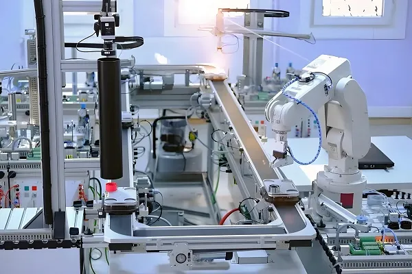
3.2 Electronic Information Field
- Application Scenarios: Micro connectors (e.g., 5G device antenna connectors), sensor housings (e.g., MEMS accelerometer housings), micro gears (e.g., micro motor gears).
- Case: MEMS sensor housing (size 5mm×3mm×1mm, wall thickness 0.1mm) made of PC material:
▶ Mold: Multi-cavity (32 cavities) design, hot runner balanced gates, micro ejector pins for demolding;
▶ Process parameters: Injection speed 200mm/s, injection pressure 180MPa, holding time 1s, cooling temperature 120℃;
▶ Quality requirements: Wall thickness tolerance ±0.005mm, no bubbles or flash, fitting clearance with sensor chip ≤ 0.01mm.
3.3 Automotive Precision Field
- Application Scenarios: Autonomous driving micro sensors (e.g., LiDAR micro lenses), micro components for engine fuel systems (e.g., micro fuel injector accessories).
- Case: LiDAR micro lens (diameter 3mm, focal length 1mm) made of optical-grade PC material:
▶ Mold: Cavity surface polished to Ra ≤ 0.02μm, single-cavity design, pneumatic demolding;
▶ Process parameters: Injection speed 100mm/s (to avoid optical performance degradation caused by melt shear), injection pressure 160MPa, cooling temperature 130℃;
▶ Quality requirements: Light transmittance ≥ 90%, optical distortion ≤ 0.1%, dimensional tolerance ±0.002mm.
Ⅳ. Common Defects and Solutions
4.1 Short Shot (Unfilled Cavity)
- Typical Phenomenon: Unformed microstructures (e.g., microchannels, micro bosses), material shortage at part edges.
- Core Causes:
-
- Insufficient injection pressure/speed, unable to overcome microcavity flow resistance;
-
- Poor mold venting, trapped air hindering melt filling;
-
- Poor material fluidity (low MFR) or insufficient melting;
-
- Excessively small gate size, blocking melt flow.
- Solutions:
▶ Process adjustment: Increase injection pressure (+20-50MPa) and injection speed (+50-100mm/s);
▶ Mold optimization: Deepen vent grooves (to 0.005mm) or add vacuum venting;
▶ Material adjustment: Replace with higher fluidity grades (e.g., LCP with higher MFR), increase barrel temperature (+10-20℃);
▶ Gate optimization: Enlarge gate size (+0.05-0.1mm) or adjust gate position to the farthest end of the cavity.
4.2 Flash (Excess Material at Part Edges)
- Typical Phenomenon: Thin edges of 0.005-0.01mm at part edges, affecting dimensional precision.
- Core Causes:
-
- Insufficient clamping force, excessive cavity clearance;
-
- Excessive injection pressure, melt overflowing the cavity;
-
- Poor mold parallelism, cavity misalignment during clamping;
-
- Excessive clearance in demolding system (e.g., clearance between ejector pin and cavity > 0.002mm).
- Solutions:
▶ Equipment adjustment: Increase clamping force (+10-30kN), ensure platen parallelism (≤0.005mm/m);
▶ Process optimization: Reduce injection pressure (-20-40MPa), shorten holding time (-0.2-0.5s);
▶ Mold maintenance: Re-grind mold parting surface to reduce cavity clearance; replace precision ejector pins to control clearance ≤ 0.002mm.
4.3 Dimensional Instability (Large Dimensional Fluctuation in the Same Batch of Parts)
- Typical Phenomenon: Deviation range of critical dimensions (e.g., hole diameter, wall thickness) > ±0.005mm.
- Core Causes:
-
- Poor injection metering precision (screw metering error > ±0.1%);
-
- Unstable mold temperature control (temperature fluctuation > ±0.5℃);
-
- Excessive material moisture content, causing shrinkage rate fluctuation;
-
- Improper adjustment of holding pressure/time, leading to uneven part shrinkage.
- Solutions:
▶ Equipment calibration: Re-calibrate the screw metering system to ensure metering precision ≤ ±0.1%; upgrade mold temperature controller to control temperature fluctuation ≤ ±0.2℃;
▶ Material pretreatment: Extend drying time (+2-4 hours) to ensure moisture content ≤ 0.02%;
▶ Process solidification: Adopt “segmented holding pressure” (high holding pressure in the early stage, low holding pressure in the late stage), record and solidify optimal holding pressure parameters.
4.4 Microstructure Deformation (e.g., Microchannel Collapse)
- Typical Phenomenon: Collapse or deformation of formed microstructures (e.g., micro bosses, micro patterns).
- Core Causes:
-
- Insufficient cooling, parts demolded before full shaping;
-
- Insufficient holding pressure, no melt supplement during part shrinkage;
-
- Improper demolding method (e.g., excessive mechanical ejection pressure);
-
- Excessively high material shrinkage rate, making it difficult to maintain microstructure shape.
- Solutions:
▶ Cooling optimization: Reduce mold cooling temperature (-10-20℃), extend cooling time (+0.5-1s);
▶ Holding pressure adjustment: Increase holding pressure (to 80% of injection pressure), extend holding time (+0.2-0.5s);
▶ Demolding improvement: Switch to pneumatic demolding (air pressure 0.2-0.5MPa) or reduce ejector pin ejection force;
▶ Material replacement: Select low-shrinkage materials (e.g., LCP instead of PP) or add glass fiber reinforcement (e.g., PA66+30% glass fiber).
Ⅴ. Quality Control and Testing Technology
5.1 Key Testing Items and Equipment
|
Testing Item
|
Testing Requirements
|
Common Equipment
|
Testing Precision
|
|
Dimensional and Form/Position Tolerance
|
Dimensional tolerance ±0.001-0.005mm, Coaxiality ≤ 0.005mm
|
Ultra-high precision CMM (e.g., Zeiss CONTURA)
|
Dimensional precision ±0.0005mm, Form/position precision ±0.001mm
|
|
Surface Roughness
|
Ra ≤ 0.1μm (cavity surface), Ra ≤ 0.2μm (part surface)
|
AFM (Atomic Force Microscope), Laser Confocal Microscope
|
AFM precision ±0.001μm, Laser Confocal ±0.01μm
|
|
Microstructure Integrity
|
No microchannel blockage, no micro boss deformation
|
SEM (Scanning Electron Microscope), Optical Microscope (200-500x)
|
SEM resolution 0.01μm, Optical Microscope ±0.005mm
|
|
Material Performance
|
Tensile strength, light transmittance, temperature resistance
|
Micro tensile testing machine (range 0-100N), UV-Vis Spectrophotometer
|
Tensile precision ±0.01N, Light transmittance ±0.1%
|
5.2 Quality Control Process
- Pre-Production Control:
-
- Material inspection: Test moisture content (Karl Fischer moisture meter) and MFR (Melt Flow Rate tester);
-
- Mold inspection: Measure cavity dimensions with CMM, test cavity surface roughness with AFM.
- In-Process Control:
-
- First-piece inspection: Full-dimensional inspection (CMM), surface quality inspection (optical microscope);
-
- In-process sampling inspection: Sample 1 piece every 50-100 pieces produced, focusing on dimensional fluctuation and microstructure integrity.
- Post-Production Control:
-
- 100% inspection of finished products: Critical parts (e.g., medical parts) require 100% inspection; ordinary parts are sampled according to AQL 0.65 (GB/T 2828.1);
-
- Failure analysis: Analyze defect causes of unqualified products with SEM to optimize processes/molds.
FAQ on Micro Injection Molding
- How to solve insufficient molding dimensional precision?
Check mold design precision, optimize gate size and position; adjust injection molding process parameters (e.g., reduce melt temperature, increase holding pressure and time) to reduce shrinkage deformation.
- What to do if parts have bubbles or voids?
Ensure sufficient material drying to remove moisture and gas; optimize mold venting structure (add vent grooves or use porous steel); adjust injection speed to avoid air entrainment due to turbulence.
- How to address incomplete microstructure replication?
Improve mold surface quality and draft angle to reduce demolding resistance; appropriately increase melt temperature and injection pressure to enhance melt fluidity; adopt mold temperature control technology to maintain stable mold temperature.
- What are the key points of equipment maintenance?
Regularly clean screws, barrels, and other components to prevent material residue degradation; check hydraulic system tightness to avoid pressure loss; conduct non-destructive testing on precision components (e.g., nozzles, mold inserts) to ensure dimensional precision.
- What are the requirements of environmental regulations for micro injection molding?
Production processes must comply with the principle of abiding by laws and regulations. Prioritize raw materials that meet environmental standards (e.g., RoHS, REACH); optimize waste recycling processes to reduce solid waste emissions; properly treat production wastewater to meet national environmental discharge standards.
Disclaimer
- All information, opinions, and data contained in this article are for the purpose of information transmission only and do not constitute any advice on investment, transactions, law, medical care, or other matters.
- The content of the article is compiled based on public information or created based on the author’s personal understanding. Although every effort is made to ensure accuracy, it does not guarantee the completeness, accuracy, and timeliness of the information, nor does it bear any responsibility for any losses caused by the use of the content of this article.
- If the article involves third-party opinions, pictures, data, and other content, the copyright belongs to the original author. In case of infringement, please contact us for deletion.
- Readers should make independent decisions based on their actual situation and combined with professional opinions. The user shall bear all consequences arising from the use of the content of this article.
Author: