Introduction: Unlocking Core Technology for Unconventional Part Manufacturing
When you encounter a shaft part with misaligned axes on your design drawing, do you feel challenged? This type of “eccentric” part cannot be processed using conventional turning methods, and this is exactly where CNC eccentric turning demonstrates its capabilities.
As an advanced skill in CNC turning, eccentric turning is widely used in critical components such as engine crankshafts, camshafts, and eccentric fixtures. Mastering its principles and methods is a key step in unlocking complex part manufacturing capabilities.
This article will take you from scratch, explaining in-depth and easy-to-understand terms the complete knowledge system of eccentric turning, from basic principles to four practical methods, and then to common problem solving, helping you completely overcome this technical difficulty.
Chapter 1: Basic Understanding – What is Eccentric Turning?
1.1 Core Definition
Eccentric turning refers to a turning method where the rotational axis of the part does not coincide with the spindle axis of the machine tool, with a preset offset distance. Simply put, it means making the centerline of the workpiece offset by a certain distance from the centerline of the machine spindle for processing.
1.2 Vivid Analogy
If conventional turning is compared to a “top rotating around its center”, then eccentric turning is like a “wobbling top with offset center of gravity”. In conventional turning, the tool rotates and cuts along the natural center of the workpiece; while in eccentric turning, we artificially make the workpiece rotate “eccentrically” to machine parts with special shapes.
1.3 Key Terminology Explanation
Eccentric distance (e):This is the core parameter of the entire process, referring to the offset distance between two parallel axes (workpiece axis and spindle axis). The size of the eccentric distance directly determines the eccentricity and final shape of the part.
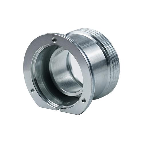
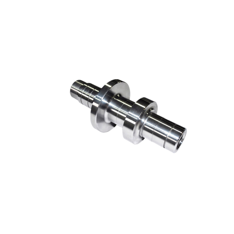
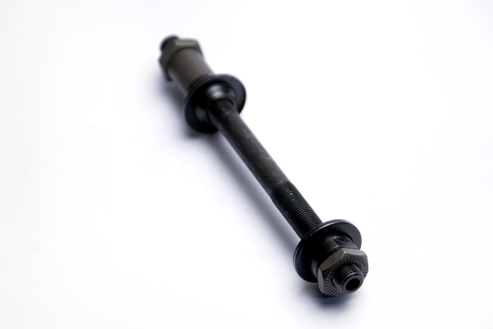
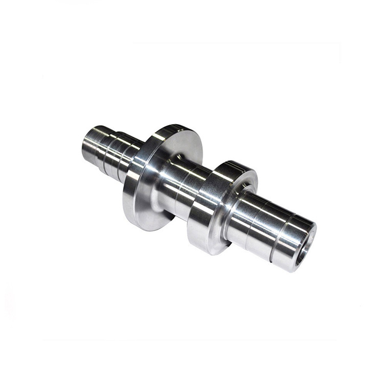
Eccentric shaft:A workpiece where the axes of the outer circles are parallel but not coincident is called an eccentric shaft.
Eccentric sleeve:A workpiece where the axis of the outer circle is parallel but not coincident with the axis of the inner hole is called an eccentric sleeve.
Chapter 2: Value and Applications – Why Do We Need Eccentric Turning?
2.1 Functional Value
Eccentric structures play irreplaceable important roles in mechanical design:
Realizing reciprocating motion conversion:Converting rotational motion to reciprocating linear motion, or vice versa
Variable speed motion control:Achieving complex motion laws through eccentric mechanisms
Clamping function implementation:Designing quick clamping mechanisms using eccentric principles
Vibration generation:Manufacturing vibrating screens, massagers and other equipment requiring vibration
2.2 Typical Application Scenarios
Automotive field
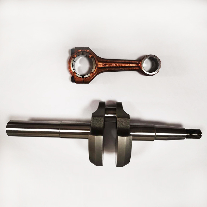
- Engine crankshaft:Converting reciprocating motion of pistons to rotational motion of crankshaft
- Camshaft:Controlling valve opening and closing timing
- Eccentric bearing:Used in suspension systems and transmission mechanisms
Industrial field
- Eccentric wheel:Transmission components for various automation equipment
- Cam mechanism:Achieving complex motion trajectories
- Eccentric fixture:Tooling for quickly clamping workpieces
General machinery
- Valve components:Special valve structures for fluid control
- Pump body parts:Core components of various types of pumps
- Vibration equipment:Vibrating screens, feeders, etc.
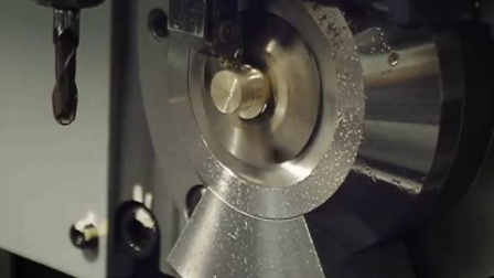
Chapter 3: Core Technology – How to Implement Eccentric Turning?
This is the technical core of eccentric turning. Mastering the following four methods will enable you to handle most eccentric machining requirements.
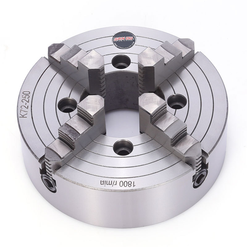
3.1 Four-Jaw Independent Chuck Clamping Method
Principle:By independently adjusting four jaws, artificially offset the rotational center of the blank by an eccentric distance.
Operation steps:
- Precisely mark lines on the workpiece to determine the eccentric circle and cross lines
- Mount the workpiece in a four-jaw chuck
- Use a dial indicator to adjust each jaw individually to align the eccentric axis with the spindle axis
- Repeatedly check and adjust until precision requirements are met
Advantages:
- Strong versatility, suitable for workpieces of various shapes
- Large adjustment range, can achieve large eccentric distances
- No need for special tooling
Disadvantages:
- Extremely time-consuming alignment process, low efficiency
- Extremely high skill requirements for operators
- Precision difficult to guarantee, poor consistency
- High labor intensity
Applicable scenarios:Single piece, small batch, large eccentric distance, low precision requirements
3.2 Three-Jaw Chuck with Eccentric Shims/Sleeves Method
Principle:Pre-manufacture a sleeve with eccentric inner and outer circles, insert the workpiece into the sleeve’s inner hole, then use the sleeve’s outer circle for positioning in the three-jaw chuck.
Shim thickness calculation formula:
X = 1.5e × (1 – e/2d) + K
Where:
- X = Shim thickness
- e = Workpiece eccentricity
- d = Diameter of the part clamped by three jaws
- K = Correction coefficient, adjusted according to actual conditions
Advantages:
- Simple operation, high efficiency
- Once shims are made, quick batch production is possible
- Relatively stable precision
- Lower cost
Disadvantages:
- Need to customize special tooling for different workpieces and eccentric distances
- Significant initial preparation work
- Limited adjustment range for eccentric distance
Applicable scenarios:Batch production, small eccentric distance, medium precision requirements
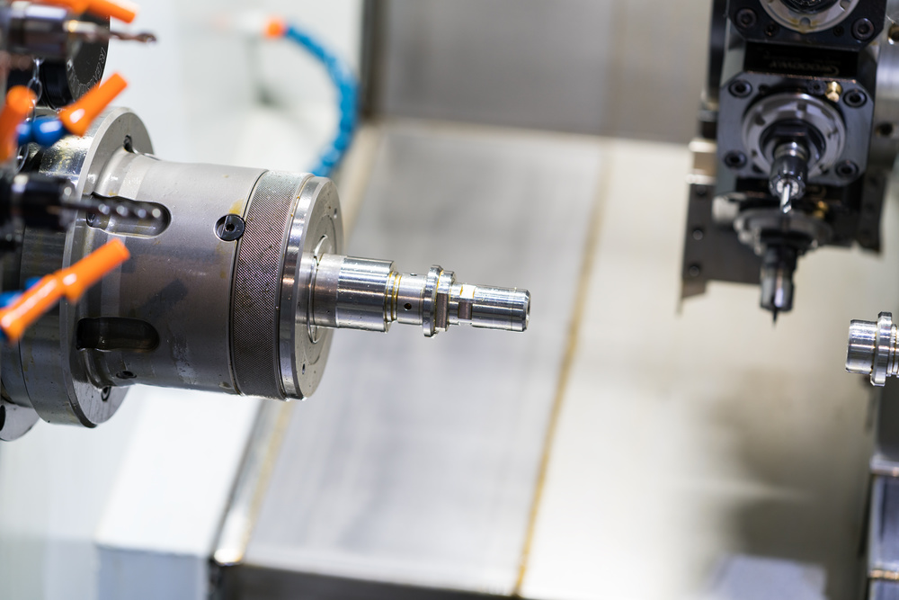
3.3 Dual-Spindle Turning Center Secondary Clamping Method
Principle:After completing reference machining on the first spindle, the sub-spindle grabs the workpiece and rotates it with the new offset axis to machine the eccentric part.
Process flow:
- Spindle 1 machines the reference part and clamping part of the workpiece
- Sub-spindle moves to the set eccentric position
- Sub-spindle grabs and clamps the workpiece
- Spindle 1 releases, sub-spindle drives the workpiece to rotate eccentrically
- Tool machines the eccentric part
Advantages:
- Complete all machining in one clamping
- Extremely high precision, good consistency
- Highest automation level
- Can machine complex multi-eccentric parts
Disadvantages:
- Huge equipment investment
- High programming requirements
- High maintenance costs
Applicable scenarios:Large batch, high precision, complex process parts, such as automotive engine crankshafts
3.4 Turn-Mill Compound Programming Method
Principle:Utilize CNC system functions such as “coordinate system rotation”, “polar coordinate interpolation” or “C-axis contour milling”, through programming commands to virtually create an offset rotation center, and use rotating tools for “turning” processing while the workpiece is stationary or indexed.
Programming points:
- Use G68 coordinate system rotation command
- Utilize polar coordinate programming (G15/G16)
- C-axis positioning and contour control
- Live tool turret milling function
Advantages:
- No need for special tooling, extremely high flexibility
- Very suitable for complex multi-eccentric parts
- Convenient programming adjustments
- Can achieve high-precision machining
Disadvantages:
- High requirements for programming and machine tool functions
- Requires turn-mill compound center equipment
- Relatively low machining efficiency
Applicable scenarios:Turn-mill compound centers with live tool turrets, small batch high-precision complex parts
3.5 Comparative Analysis of Four Methods
|
Method
|
Precision Level
|
Efficiency
|
Cost
|
Applicable Batch
|
Eccentricity Range
|
Equipment Requirement
|
|
Four-Jaw Chuck
|
±0.02-0.05mm
|
Low
|
Low
|
Single piece small batch
|
Large
|
Ordinary lathe
|
|
Shim/Sleeve
|
±0.01-0.03mm
|
Medium
|
Medium
|
Small to medium batch
|
Small
|
Ordinary lathe
|
|
Dual-Spindle
|
±0.005-0.01mm
|
High
|
High
|
Large batch
|
Medium
|
Dual-spindle turning center
|
|
Programming
|
±0.003-0.008mm
|
Medium
|
High
|
Small to medium batch
|
Medium
|
Turn-mill compound center
|
Chapter 4: Practical Guide – Challenges and Solutions in Eccentric Turning
4.1 Core Challenge: Imbalance and Vibration
Problem analysis:
During eccentric machining, due to uneven mass distribution, high-speed rotation produces huge centrifugal force, leading to severe vibration and noise. This not only affects machining quality but may also damage machine tools and tools.
Solutions:
1. Counterweight balancing method
- Install counterweight blocks at symmetrical positions of the workpiece
- Counterweight mass = eccentric mass × eccentric distance / counterweight distance
- Suitable for single piece small batch production
2. Speed reduction method
- Reduce spindle speed to safe range
- Calculation formula: n ≤ 1200 / √e (n is rotational speed r/min, e is eccentricity mm)
- Most direct and effective method, but affects efficiency
3. Support enhancement method
- Use tailstock center to support the workpiece
- For long shaft eccentric parts, tailstock support is essential
- Improve system rigidity and reduce vibration
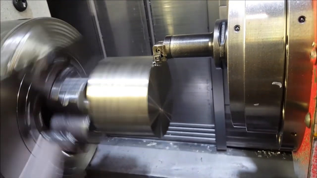
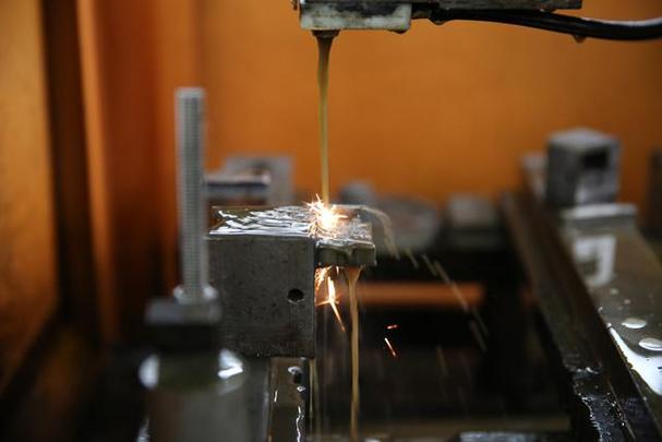
4.2 Tool and Cutting Parameter Optimization
Tool selection:
- Material:Choose carbide with good toughness, such as WC-Co alloy
- Coating:TiAlN or AlCrN coating to improve wear resistance
- Groove type:Choose chip breaker groove suitable for stainless steel and alloy steel
- Tool nose radius:Appropriately increase tool nose radius to improve strength
Cutting parameter settings:
- Cutting speed:30-50% lower than conventional turning
- Feed rate:Use moderate feed to avoid vibration
- Cutting depth:Layered cutting, 0.1-0.3mm per layer
- Cooling:Adequate cooling, use high-pressure coolant
4.3 Measurement and Inspection Techniques
Eccentricity measurement methods:
1. Dial indicator measurement method
- Mount the workpiece between centers
- Dial indicator contact touches the eccentric outer circle
- Rotate the workpiece, the difference between maximum and minimum dial indicator readings equals 2e
- Simple and intuitive, suitable for small eccentric distances
2. V-block measurement method
- Place the workpiece on equal-height V-blocks
- Use dial indicator to find the highest point
- Calculate eccentricity through calculation
- Suitable for workpieces with large eccentric distances
3. Coordinate measuring method
- Use CMM for precise measurement
- Can measure complex 3D eccentricity
- Highest precision but also highest cost
4.4 Common Problems and Solutions
Problem 1: Machined surface has chatter marks
- Causes:Excessive speed, insufficient rigidity, tool wear
- Solutions:Reduce speed, increase support, replace tools
Problem 2: Dimensional accuracy instability
- Causes:Insufficient clamping force, thermal deformation, tool wear
- Solutions:Increase clamping force, adequate cooling, regular tool changes
Problem 3: Short tool life
- Causes:Improper cutting parameters, wrong tool selection, insufficient cooling
- Solutions:Optimize parameters, select appropriate tools, strengthen cooling
Problem 4: Low machining efficiency
- Causes:Conservative parameters, unreasonable process, equipment limitations
- Solutions:Reasonably optimize parameters, improve processes, upgrade equipment
Chapter 5: Industry Application Case Analysis
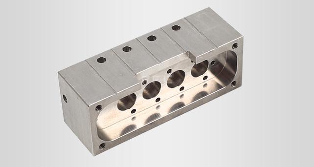
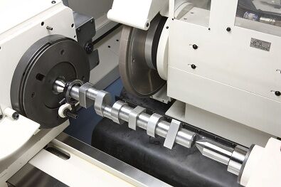
5.1 Automotive Engine Crankshaft Machining
Processing difficulties:
- Multi-throw eccentricity, high angle precision requirements
- Strict balance requirements
- Material is high-strength alloy steel
Solutions:
- Use special crankshaft lathes
- Adopt dual-spindle machining technology
- Equip with automatic balancing system
- Online inspection and compensation
Technical parameters:
- Eccentricity precision: ±0.005mm
- Angle precision: ±15″
- Surface roughness: Ra0.8μm
5.2 Industrial Eccentric Cam Machining
Processing difficulties:
- Complex cam profiles
- High precision requirements
- High material hardness
Solutions:
- Use turn-mill compound centers
- Adopt C-axis contour milling
- High-precision tooling system
5.3 Medical Device Eccentric Shaft Machining
Processing difficulties:
- Materials are titanium alloy or stainless steel
- High surface finish requirements
- Biocompatibility requirements
Solutions:
- Special fixture design
- High-precision machining centers
- Electrolytic polishing treatment
Chapter 6: Future Development Trends
6.1 Technology Development Directions
1. Intelligent machining
- AI-driven parameter optimization
- Adaptive vibration control
- Predictive maintenance
2. High-precision development
- Nanoscale precision control
- Real-time error compensation
- Online inspection technology
3. Green manufacturing
- Energy-saving machining processes
- Environmentally friendly cutting fluids
- Waste recycling and utilization
6.2 Equipment Development Trends
1. Multi-functional compound machine tools
- Turn-mill-grind compound machining
- Combination of 3D printing and CNC
- Integrated online measurement
2. Automated production lines
- Robot loading and unloading
- Flexible manufacturing systems
- Digital twin technology
Conclusion: Mastering Eccentric Turning, Opening New Manufacturing Possibilities
Eccentric turning is not unattainable; its core lies in precise control of the “eccentric distance”. Whether through tooling guarantees or programming implementation, choosing the right solution is the key to success.
Core points review:
- Basic understanding:Understand the concept and function of eccentricity
- Method selection:Choose appropriate machining methods based on batch size, precision, and cost
- Problem solving:Master vibration control and parameter optimization techniques
- Quality assurance:Establish a complete measurement and inspection system
Action recommendations:
- Start with small batches:Practice with simple parts first to accumulate experience
- Invest in appropriate equipment:Choose equipment configuration based on actual needs
- Cultivate professional talents:Strengthen technical training to improve operational skills
- Establish standard processes:Develop standardized technical documents
Mastering eccentric turning technology will bring new competitive advantages to your enterprise and open up new possibilities for complex part manufacturing. Whether you are a manufacturing engineer, technical manager, or entrepreneur, this technology will become your key to unlocking high-end manufacturing.
Start your eccentric turning journey now! Begin with simple eccentric shafts, gradually master the machining techniques for complex parts, and keep advancing on the path of precision manufacturing.
This article is based on actual production experience and technical materials, ensuring accurate and reliable content. When applying in practice, adjustments and optimizations should be made according to specific conditions.