Seamless integration of CAD (design), CAM (tool-path), and CNC (execution) turns a digital model into a finished part in minutes, not days.
1. Data Flow Overview
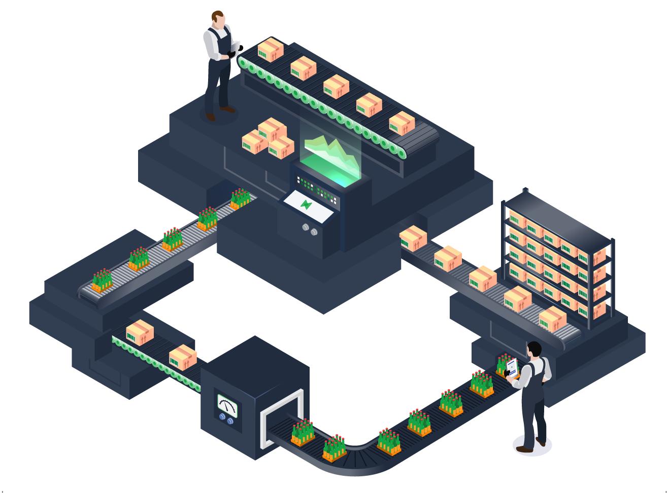
The integration follows a closed-loop pipeline: CAD → CAM → Post-Processor → CNC → Feedback → CAD/CAM. Each stage is automated, eliminating manual re-entry and reducing errors .

2. Step-by-Step Workflow
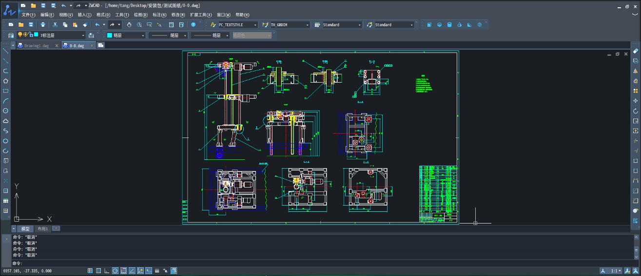
2.1 CAD Model Export
Design the part in any CAD package (SolidWorks, Fusion 360, NX). Export as STEP, IGES, or Parasolid to preserve geometry and PMI .
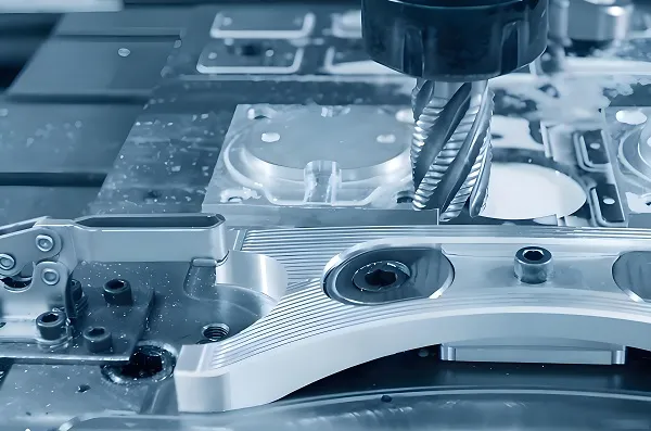
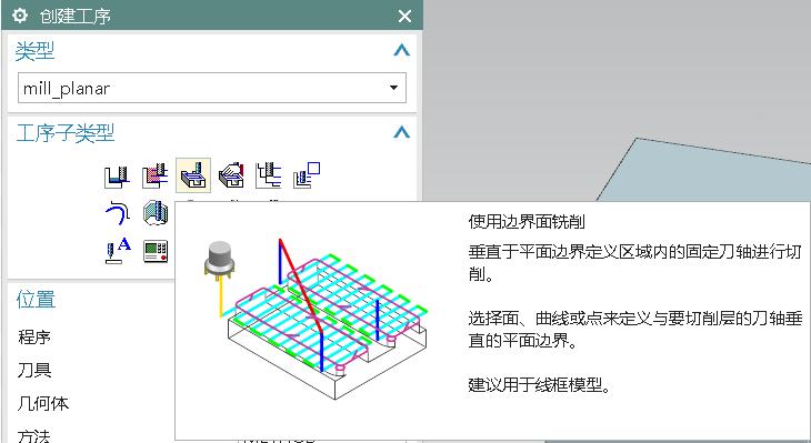
2.2 CAM Setup & Tool-Path Generation
Stock Definition: Define raw material size and orientation.
Work Coordinate System (WCS): Align model with machine axes.
Tool Selection: Pick cutters from integrated tool library; feeds & speeds auto-populate based on material .
Operation Planning: Roughing, semi-finishing, finishing—each optimized for cycle time and surface finish.
Path Calculation: CAM software computes collision-free, gouge-free tool-paths using high-efficiency strategies like adaptive clearing or trochoidal milling .
2.3 Simulation & Verification
Run kinematic simulation to detect collisions, over-travel, and excess material. Adjust parameters in real time .
2.4 Post-Processing to G-code
A post-processor tailors generic tool-path data into machine-specific G-code (Fanuc, Siemens, Heidenhain, etc.) . Modern CAM suites include >1,000 certified post-processors.
2.5 DNC Transfer & Execution
API/Plugin Push: One-click transfer via secure API or dedicated CAM-DNC plugin .
Checksum & Versioning: Automatic file verification prevents outdated programs from running.
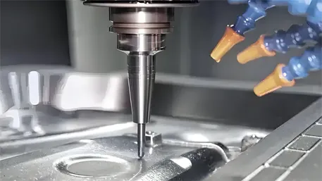
On-Machine Verification: Optional probing cycles confirm fixture and part offsets before full run.
2.6 Closed-Loop Feedback
CNC controller streams real-time spindle load, tool wear, and dimensional data back to CAM for adaptive tool-path updates and predictive maintenance .
3. Integration Architectures
|
Architecture
|
Description
|
Benefit
|
|
Standalone CAM
|
CAD export → CAM import → Post → USB/DNC
|
Low cost, flexible
|
|
Integrated CAD/CAM
|
Single platform (e.g., Fusion 360, NX)
|
No data loss, instant updates
|
|
Cloud SaaS
|
Browser-based CAM with direct machine link
|
Remote collaboration, auto-scaling
|
4. Practical Tips
• Standardize Formats: Stick to STEP/AP242 for PMI retention.
• Post-Processor Validation: Run a dry-run on a sacrificial part before production.
• Tool Library Sync: Keep CAM tool library mirrored with physical tool crib via RFID or barcode.
• Incremental Back-Plotting: Use back-plot software to visualize G-code motion and catch syntax errors early.
Disclaimer
All experimental data presented in this paper are derived from controlled production environments and standardized test procedures. However, due to differences in equipment models, material batches, and on-site operating conditions, readers are advised to verify and adjust technical parameters according to their specific application scenarios before practical implementation.
The research results and technical insights shared herein are based on the author’s professional experience and experimental observations. The author and the affiliated institution shall not be liable for any direct, indirect, or consequential damages (including but not limited to equipment damage, product quality issues, or production losses) arising from the improper use of the information provided in this paper.
This paper reflects the author’s personal research findings and does not necessarily represent the official views of the affiliated institution or any collaborating enterprises.
All trademarks and product names mentioned (e.g., FANUC, DMG MORI, Siemens Sinumerik ONE) are the property of their respective owners, and their inclusion does not imply endorsement or recommendation by the author.