CNC (Computer Numerical Control) machines automate manufacturing by following programmed instructions to shape materials like metal, plastic, or wood. Their operation involves six key steps, from design to finished part.
Step 1: Design the part (CAD modeling)
The process starts with creating a 3D digital model of the desired part using CAD (Computer-Aided Design) software (e.g., Fusion 360, SolidWorks). This model defines the part’s dimensions, geometry, and features (e.g., holes, grooves, or curves).
- Key goal: Produce a precise digital blueprint that includes all critical details, such as tolerances (e.g., ±0.001 inches) and surface finish requirements.
- Example: A CAD model for a metal bracket might specify a 2-inch length, 0.5-inch thickness, and a 0.25-inch diameter hole centered 0.75 inches from the edge.
Step 2: Convert the design to machine instructions (CAM programming)
The CAD model is imported into CAM (Computer-Aided Manufacturing) software, which translates the 3D design into a set of machine-readable instructions called G-code (the standard CNC language).
- What CAM does:
- Selects appropriate cutting tools (e.g., end mills, drills) based on the material and part features.
- Generates toolpaths: The path the cutting tool will follow to remove material, optimized for efficiency and safety (e.g., avoiding collisions with the machine or workpiece).
- Sets parameters like spindle speed (how fast the tool rotates, in RPM), feed rate (how fast the tool moves, in inches per minute), and depth of cut (how much material is removed per pass).
- Output: A G-code file (e.g., “bracket_program.gcode”) containing commands like G01 X2.0 Y1.5 F100 (move the tool to X=2.0, Y=1.5 at 100 inches per minute).
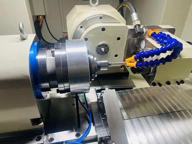
Step 3: Prepare the CNC machine and workpiece
Before machining, the operator sets up the machine and secures the raw material (workpiece):
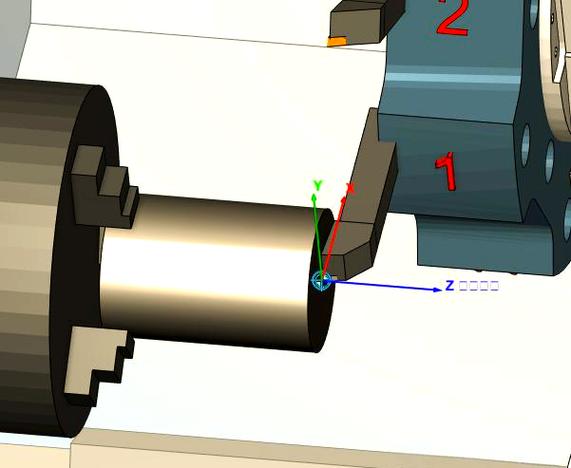
- Mount the workpiece: The material is clamped to the machine’s worktable using fixtures (e.g., vises, clamps, or custom jigs) to prevent movement during cutting.
- Load cutting tools: Tools are inserted into the machine’s tool holder or turret, with each tool assigned a specific number (e.g., Tool 1 = 1/4-inch end mill) matching the CAM program.
- Set work offsets: The operator calibrates the machine’s coordinate system to align the workpiece with the digital model. This involves touching the tool to a reference point (e.g., the workpiece’s edge) and storing its position in the CNC controller.
Step 4: Load and verify the program
The G-code file is loaded into the CNC machine’s controller (via USB, network, or SD card). The operator reviews the program to check for errors:
- Simulation: Most controllers let operators simulate the toolpath on-screen to visualize cutting movements, ensuring no collisions between the tool, workpiece, or machine components.
- Test run: For critical parts, a “dry run” (no cutting, tool moving in air) or a test on scrap material may be performed to validate toolpaths and parameters.
Step 5: Execute the machining process
Once verified, the operator starts the program. The CNC machine automatically follows the G-code instructions:
- Tool movement: The machine’s axes (e.g., X, Y for horizontal movement; Z for vertical movement) move the cutting tool along the programmed path. For 3D parts, multi-axis machines (e.g., 5-axis) adjust the tool’s angle to reach complex surfaces.
- Material removal: The rotating tool cuts, drills, or grinds away excess material, gradually shaping the workpiece into the CAD model’s form. Coolant is often sprayed to reduce heat and flush away chips (debris).
- Real-time monitoring: Sensors or cameras may track the process, pausing the machine if issues (e.g., tool breakage, excessive vibration) are detected.
Step 6: Inspect and finish the part
After machining, the workpiece is removed from the machine for inspection and post-processing:
- Quality check: Measurements are taken with tools like calipers, micrometers, or CMMs (Coordinate Measuring Machines) to ensure the part meets dimensional tolerances and surface finish standards.
- Finishing: Excess material (e.g., burrs) is removed via deburring, sanding, or polishing. Some parts may undergo additional treatments (e.g., painting, plating) depending on requirements.
Why is this process efficient?
CNC machining eliminates manual labor for cutting, ensuring consistency (identical parts across batches), precision (tolerances as tight as ±0.0001 inches), and automation (24/7 operation with minimal oversight). While setup is time-consuming, it’s far faster than manual machining for complex or high-volume parts.
Conclusion
From CAD design to finished part, CNC machining relies on digital precision and automated tool movement to transform raw materials into accurate, repeatable components. Each step—design, programming, setup, execution, and inspection—works together to deliver high-quality results across industries like aerospace, automotive, and medical manufacturing.