Comprehensive Technical Analysis for B2B Manufacturing Professionals
Industry: Injection Molding |
Target Audience: Engineers, Purchasers, Quality Control Specialists
Executive Summary
Injection molding accounts for 32% of global polymer processing (Grand View Research, 2024) and remains the backbone of mass production across automotive, medical devices, and consumer electronics. The industry is witnessing a 5.8% CAGR growth, driven by demand for precision components and sustainable manufacturing solutions.
Key Performance Indicators (KPIs)
- Cycle Time Reduction: 18% improvement with pulsed cooling technology
- Dimensional Accuracy: ±0.01mm positional repeatability
- Energy Savings: 40% reduction with self-heating molds
- Tooling Life: 5 million cycles with hybrid mold materials
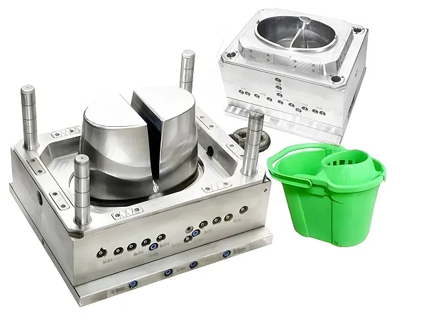
Core Components & Working Principle
Mold Architecture (Patent-inspired Design)
Key Components Specifications:
- Clamping Unit: 800-3,500 ton force range for automotive-grade molds
- Injection System: Screw L/D ratio 20:1~25:1 for optimal melt homogenization
- Cooling Channels: Conformal circuits achieving ±0.5°C thermal variance
- Ejection Mechanism: 3-stage servo-controlled ejection with <0.01mm positional repeatability
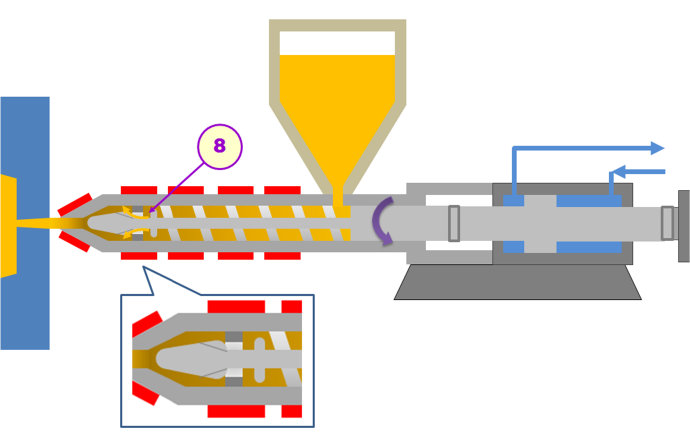
Detailed Working Principle
Injection molding is a manufacturing process where molten material is injected into a mold cavity under high pressure, then cooled and solidified to form the final product. The process involves several key stages:
- Material Feeding: Thermoplastic pellets are fed into the hopper and transported to the heating cylinder
- Melting: The screw rotates to convey, compress, and melt the plastic material
- Injection: The molten plastic is injected into the mold cavity at high pressure (150-2000 bar)
- Packing & Holding: Additional material is packed into the cavity to compensate for shrinkage
- Cooling: The material solidifies in the mold cavity under controlled temperature
- Ejection: The finished part is ejected from the mold cavity
Material Flow Dynamics
The process follows a non-Newtonian shear-thinning behavior where viscosity (η) decreases exponentially with shear rate (γ̇):
Where K=consistency index, n=pseudoplasticity index (0.2~0.7 for most thermoplastics)
Operational Workflow: Engineer’s Perspective
Pre-Production Validation (ISO 20417:2021 Compliance)
Mold Qualification:
- Run 500-shot DOE to establish CpK>1.67
- Validate gate freeze time within 0.1s of simulation
- Verify dimensional accuracy across all cavities
- Perform surface finish inspection (Ra < 0.4μm)
Material Conditioning:
- Pre-dry resins to <300ppm moisture (e.g., PA66: 80°C/4h)
- Implement hopper loaders with -40°C dew point air
- Verify material melt flow index (MFI) before production
- Conduct material compatibility testing with mold materials
Detailed Operational Process Flow
1. Mold Setup & Preparation
- Install mold in injection molding machine
- Connect cooling lines and verify flow rates
- Install ejector system and test functionality
- Set up material feeding system
- Calibrate temperature controllers and sensors
2. Machine Startup & Warm-up
- Heat barrels to specified temperatures
- Preheat mold to operating temperature
- Purge machine with cleaning material
- Load production material into hopper
- Perform test shots to verify process stability
3. Production Operation
- Monitor process parameters in real-time
- Perform regular quality checks
- Adjust process parameters as needed
- Maintain material supply and quality
- Document production data and quality records
4. Shutdown & Maintenance
- Purge remaining material from machine
- Cool mold and machine to safe temperatures
- Clean mold surfaces and cavities
- Apply rust preventive coatings
- Store mold in controlled environment
Production Cycle Optimization
| Phase | Parameter Control | Advanced Monitoring | Quality Checks |
|---|---|---|---|
| Injection (0.5-5s) | V/P switchover at 95-98% cavity fill | Real-time cavity pressure sensors | Short shot testing, fill balance |
| Packing (2-10s) | Decay curve pressure profiling | Ultrasonic melt-front detection | Weight consistency, sink mark inspection |
| Cooling (15-60s) | ΔT<10°C between mold halves | IR thermography for hot spots | Dimensional stability, warpage measurement |
| Ejection (0.5-2s) | Z-axis acceleration <3G | Ejector pin force telemetry | Visual inspection for defects, ejection marks |
Cycle Time Reduction Case Study
By implementing pulsed cooling (5Hz oscillation in coolant flow), XYZ Corp reduced cycle times by 18% while maintaining dimensional stability (±0.05mm on 200mm parts). This translates to an additional 1,200 parts produced per 8-hour shift.
Before vs After Optimization:
- Cycle Time: 45s → 37s (18% reduction)
- Production Output: 640 parts/shift → 760 parts/shift (18% increase)
- Energy Consumption: 2.3kWh/kg → 1.9kWh/kg (17% reduction)
- Defect Rate: 2.1% → 1.2% (43% improvement)
Quality Control & Inspection Procedures
Dimensional Inspection
- Coordinate Measuring Machine (CMM) for critical dimensions
- Vision systems for automated inspection
- Go/no-go gauges for routine checks
- Laser scanning for complex geometries
Visual Inspection
- Surface defects (sink marks, weld lines, flash)
- Color consistency and appearance
- Gate vestige and ejection marks
- Assembly fit and functionality
Material Testing
- Tensile strength and elongation testing
- Impact resistance (Izod/Charpy)
- Heat deflection temperature (HDT)
- Chemical resistance testing
Materials & Processing Standards
Common Materials & Processing Parameters
| Material | Melt Temp (°C) | Mold Temp (°C) | Shrinkage (%) |
|---|---|---|---|
| PP | 200-280 | 20-80 | 1.8-2.5 |
| ABS | 220-280 | 40-90 | 0.5-0.7 |
| PA66 | 260-320 | 80-120 | 1.5-2.0 |
| PC | 280-330 | 80-120 | 0.5-0.7 |
| POM | 180-230 | 80-120 | 1.5-2.2 |
Mold Base Materials
Tool Steels
- H13: Hot work steel, good toughness and wear resistance
- S136: Stainless steel, excellent corrosion resistance
- P20: Pre-hardened steel, good polishability
- NAK80: Pre-hardened steel, excellent machinability
Aluminum Alloys
- 7075: High strength, good for prototype molds
- 6061: Good corrosion resistance, easy to machine
- 5052: Excellent formability, good weldability
- 7050: Ultra-high strength, aerospace grade
Copper Alloys
- BeCu: Excellent thermal conductivity
- CuBe2: High strength, good electrical conductivity
- Al青铜: Good wear resistance, anti-galling
- Phosphor Bronze: Excellent fatigue resistance
Materials Processable by Injection Molding
Thermoplastics
- Polypropylene (PP)
- Acrylonitrile Butadiene Styrene (ABS)
- Polyethylene (PE)
- Polyvinyl Chloride (PVC)
- Polystyrene (PS)
Engineering Plastics
- Polyamide (PA/Nylon)
- Polycarbonate (PC)
- Polyoxymethylene (POM/Acetal)
- Polyethylene Terephthalate (PET)
- Polybutylene Terephthalate (PBT)
High-Performance Plastics
- Polysulfone (PSU)
- Polyetherimide (PEI)
- Polyphenylene Sulfide (PPS)
- Polyetheretherketone (PEEK)
- Polyimide (PI)
Specialty Materials
- Thermoplastic Elastomers (TPE)
- Biodegradable Polymers
- Conductive Plastics
- Glass-Filled Composites
- Mineral-Filled Compounds
International Standards Compliance
ISO Standards
- ISO 20417:2021 – Injection molding quality management
- ISO 9001:2015 – Quality management systems
- ISO 13485:2016 – Medical device quality management
ASTM Standards
- ASTM D3641 – Injection molding of thermoplastics
- ASTM D638 – Tensile properties of plastics
- ASTM D790 – Flexural properties of plastics
Industry Specific
- IATF 16949:2016 – Automotive industry quality
- FDA 21 CFR Part 177 – Food contact materials
- UL 94 – Flammability testing
Cutting-Edge Innovations
Self-Heating Molds
Induction-heated cores (patent pending) enable:
- 40% energy savings vs. conventional oil heating
- 100ms response time for dynamic thermal zoning
- Reduced cycle time by 25% for thick-walled parts
Microcellular Foaming (MuCell® Technology)
Supercritical fluid (N2/CO2) injection technology:
- Reduces part weight by 15-30%
- Eliminates sink marks in ribs >4:1 aspect ratio
- Improves dimensional stability by 35%
Smart Mold Integration
IoT-enabled mold monitoring systems:
- Piezoelectric sensors detect micro-flash at <50μm level
- Edge computing predicts maintenance needs with 92% accuracy
- Real-time quality control with 99.7% detection rate
Test Data & Performance Metrics (For Reference Only)
| Technology | Energy Savings | Cycle Time Reduction | Quality Improvement |
|---|---|---|---|
| Self-Heating Molds | 40% ±5% | 25% ±3% | 15% better surface finish |
| MuCell® Foaming | 20% ±4% | 30% ±5% | 35% better dimensional stability |
| Smart Monitoring | 15% ±3% | 18% ±4% | 99.7% defect detection rate |
* Test data based on controlled laboratory conditions, actual results may vary
Critical Challenges & Solutions
Q1: Why does amorphous shrinkage differ between PP and ABS?
Engineer’s Insight:
PP’s semi-crystalline structure causes 1.8-2.5% volumetric shrinkage (orientation-dependent), while amorphous ABS exhibits 0.5-0.7% isotropic shrinkage.
Mitigation Strategies:
- Mold temp control: PP@40-80°C vs ABS@60-90°C
- Gate positioning: Balance flow lengths for PP’s high molecular orientation
- Packing pressure optimization: 15-20% higher for PP vs ABS
Q2: How to eliminate weld lines in optical components?
Proven Approach:
- Increase melt temp to upper processing limit (e.g., PC from 300°C→320°C)
- Implement vacuum venting (≤5mbar) at weld locations
- Use sequential valve gating with 0.02s overlap timing
- Apply mold surface texturing to mask minor weld lines
Q3: How to prevent screw slippage with high-glass-fiber materials?
Technical Solution:
Use stepped screw design with 25° flight angle in feed zone. Maintain 85-95% screw torque load for optimal shear mixing without degradation.
- Implement barrier screw design for better melting
- Use wear-resistant screw coatings (Ni-PTFE)
- Optimize feed zone temperature to 80-120°C
Q4: Best practices for mold storage in humid environments?
Preventive Maintenance:
- Apply VCI (Vapor Corrosion Inhibitor) coating
- Maintain 35% RH with desiccant breathers
- Perform monthly EDM reconditioning on parting surfaces
- Use rust-preventative oils with corrosion inhibitors
Applications, Advantages & Usage
Primary Uses of Injection Molds
Mass Production
Injection molding is ideal for producing large quantities of identical parts with high precision and consistency.
- Consumer electronics components
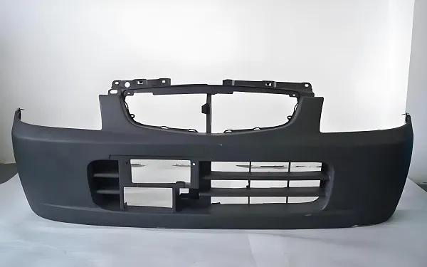
- Automotive interior and exterior parts
- Packaging containers and closures
- Household appliances and utensils
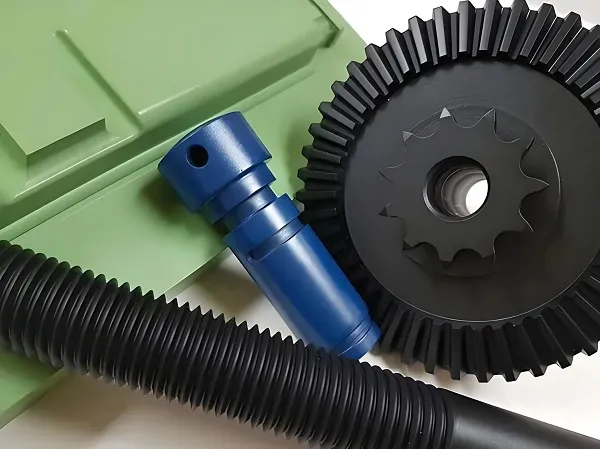
Complex Geometry
The process can create intricate shapes and features that would be difficult or impossible with other manufacturing methods.
- Medical device components
- Aerospace parts with complex contours
- Interlocking assemblies
- Parts with integrated hinges and snaps
Material Versatility
Injection molding supports a wide range of materials with different properties to meet specific application requirements.
- High-temperature resistant plastics
- Chemical resistant materials
- Conductive and insulating compounds
- Biocompatible materials for medical use
Key Advantages of Injection Molding
High Precision
Dimensional accuracy of ±0.01mm can be achieved, making it suitable for tight tolerance applications.
Cost Efficiency
Low per-unit cost for high-volume production runs, with minimal material waste.
Fast Production
Cycle times can be as short as 10 seconds, enabling high throughput and quick turnaround.
Design Flexibility
Supports complex geometries, multiple materials, and integrated features in a single part.
Consistency
Excellent repeatability ensures every part meets the same quality standards.
Automation Friendly
Easily integrated with robotics and automation systems for unmanned operation.
Industry Applications
| Industry | Typical Products | Materials Used | Key Requirements |
|---|---|---|---|
| Automotive | Bumpers, dashboards, engine components | PP, ABS, PA66, PBT | High impact resistance, heat stability |
| Medical | Syringes, surgical instruments, implant components | PC, PE, PP, PEEK | Biocompatibility, sterilizable, FDA compliant |
| Electronics | Phone cases, connectors, circuit boards | ABS, PC, PBT, LCP | Electrical insulation, flame retardant |
| Packaging | Bottle caps, containers, closures | PP, PE, PET, PS | Food contact safe, high clarity |
| Aerospace | Interior panels, structural components | PEEK, PEI, PPS, PSU | High temperature resistance, low weight |
| Consumer Goods | Toys, kitchenware, personal care products | PP, ABS, PS, TPE | Color stability, impact resistance |
Usage Guidelines & Best Practices
Mold Maintenance
- Regular cleaning of mold surfaces
- Lubrication of moving parts
- Inspection for wear and damage
- Replacement of worn components
- Storage in controlled environment
Process Optimization
- Optimize temperature profiles
- Adjust injection pressure and speed
- Control cooling time effectively
- Monitor and maintain material quality
- Implement statistical process control
Quality Control
- Regular dimensional inspection
- Visual inspection for defects
- Material testing and verification
- Environmental testing (temperature, humidity)
- Failure analysis and corrective actions
Design Development & Customization
Mold Design Process
- Conceptual Design: Initial design based on product requirements, material selection, and manufacturing constraints
- DFM Analysis: Design for Manufacturing analysis to optimize moldability and reduce production costs
- 3D Modeling: Detailed 3D CAD modeling of mold components and assembly
- Simulation & Analysis: Mold flow simulation to predict filling, cooling, and warpage
- Tool Path Generation: CNC programming for mold machining operations
- Prototype Testing: Rapid prototyping and testing to validate design concepts
- Final Design Approval: Design review and approval before manufacturing
Design Considerations
- Part geometry and complexity
- Material properties and flow characteristics
- Mold cooling and ejection system
- Gate location and runner system design
- Tolerance requirements and surface finish
- Production volume and cycle time targets
- Maintenance and serviceability
Customization Capabilities
Multi-Cavity Molds
Custom molds with multiple cavities to produce multiple parts in a single cycle, increasing production efficiency.
- 1-128 cavity configurations available
- Balanced runner systems for uniform filling
- Individual cavity pressure monitoring
- Quick change inserts for different part designs
Family Molds
Molds that produce different parts in the same cycle, ideal for assembly kits and multi-component products.
- Different part geometries in one mold
- Optimized gating for each part
- Common cooling system design
- Reduced tooling costs compared to separate molds
Insert Molding
Process where pre-inserted components are encapsulated in plastic during molding.
- Metal inserts for strength and conductivity
- Electronic components encapsulation
- Threaded inserts for assembly
- Precision alignment systems
Overmolding
Process where a second material is molded over an existing part to create a composite structure.
- Soft-touch grips and handles
- Multi-color parts and logos
- Sealing and gasketing applications
- Enhanced ergonomics and aesthetics
Design Validation & Testing
Mold Flow Simulation
- Fill time analysis and optimization
- Weld line prediction and minimization
- Air trap detection and solution
- Cooling time calculation and optimization
- Warpage prediction and correction
Structural Analysis
- Stress analysis of mold components
- Deflection calculation and reinforcement
- Fatigue life prediction
- Ejection force calculation
- Clamping force requirement analysis
Prototyping & Testing
- 3D printed prototype molds
- Short run production testing
- Dimensional accuracy verification
- Surface finish evaluation
- Functional testing of molded parts
Future Outlook & Industry Trends
Industry 4.0 Integration
The industry is transitioning toward closed-loop rheology control systems that auto-adjust shot parameters based on real-time melt viscosity readings. Emerging hybrid molds combining metal 3D printing (conformal cooling) and ceramic composites (abrasion resistance) promise to push tooling life beyond 5 million cycles.
AI & Machine Learning
- Predictive maintenance with 95% accuracy
- Real-time process optimization
- Quality prediction before part ejection
Sustainability Focus
- 100% recycled material processing
- Carbon-neutral manufacturing by 2035
- Zero-waste production systems
Advanced Materials
- Biodegradable thermoplastics
- High-temperature composites
- Conductive polymers
Market Projections (2026-2030)
| Segment | CAGR (%) | Market Size (USD Billion) | Key Drivers |
|---|---|---|---|
| Smart Molds | 12.3% | $8.2B | Industry 4.0 adoption |
| Medical Molding | 8.7% | $12.5B | Aging population demand |
| Automotive Components | 6.2% | $18.9B | Electric vehicle growth |
| Sustainable Materials | 15.8% | $5.7B | Environmental regulations |
Ready to Optimize Your Injection Molding Process?
Our team of experienced engineers can help you achieve higher quality, faster cycles, and lower costs.