CNC cutting—short for Computer Numerical Control cutting—has revolutionized how industries from aerospace to automotive, medical device manufacturing to custom prototyping produce precise, consistent parts. Unlike traditional manual cutting, which relies on human skill and is prone to error, CNC cutting uses computer programming to automate tool movement, delivering repeatable accuracy down to ±0.005mm. For engineers, small-batch producers, or anyone learning manufacturing, understanding how CNC cutting works is critical to optimizing workflows, reducing waste, and ensuring parts meet strict design standards.
This guide breaks down the CNC cutting process into clear, actionable steps, explains core principles, and addresses real-world considerations (like equipment selection, material compatibility, and troubleshooting) to help you apply this technology effectively.
1. What Is CNC Cutting, and How Does It Differ From Traditional Cutting?
Before diving into the process, it’s essential to define CNC cutting and its key advantages over manual methods:
CNC cutting is a subtractive manufacturing technique where a computer controls the movement of cutting tools (e.g., endmills, lasers, plasma torches) to remove material from a workpiece, shaping it into a pre-designed 2D or 3D part. The “numerical control” refers to the code (G-code) that translates digital designs into precise tool paths—eliminating human error and enabling 24/7 operation.
|
Feature
|
CNC Cutting
|
Traditional Manual Cutting
|
|
Accuracy
|
Repeatable (±0.005–0.02mm)
|
Dependent on operator skill (±0.1mm+)
|
|
Efficiency
|
Fast; ideal for high-volume or complex parts
|
Slow; limited by human speed
|
|
Consistency
|
Identical parts across batches
|
Variations between parts
|
|
Complexity
|
Handles intricate shapes (e.g., curved surfaces, holes)
|
Limited to simple geometries
|
For example, a custom automotive shop producing 50 aluminum brackets would use CNC cutting to ensure every bracket has identical hole positions and edge smoothness—something manual grinding or sawing could never guarantee.
2. Core Principles of CNC Cutting
At its heart, CNC cutting relies on three interconnected systems to work:
- Computer Control System: The “brain” of the operation, typically a CNC controller (e.g., Fanuc, Siemens) that reads G-code (the programming language for CNC machines) and sends signals to the machine’s motors.
- Servo Motor System: Converts electrical signals from the controller into precise mechanical movement. Servo motors drive the machine’s axes (e.g., X, Y, Z for 3-axis machines; additional axes for 5-axis cutting) to position the tool or workpiece.
- Cutting Tool System: The tool (e.g., endmill, laser, plasma) that removes material. Tool selection depends on the material (e.g., metal vs. plastic) and desired finish (e.g., smooth edges vs. rapid cutting).
Together, these systems ensure the tool follows the exact path defined in the design—even for complex, multi-step cuts.
3. Step-by-Step Process of CNC Cutting
CNC cutting is not a single “push-button” step; it’s a structured workflow that begins with design and ends with quality inspection. Below is a detailed breakdown of each phase, with real-world examples to illustrate key considerations.
Step 1: Design the Part (CAD Modeling)
Every CNC cut starts with a digital design. This step uses Computer-Aided Design (CAD) software (e.g., SolidWorks, AutoCAD, Fusion 360) to create a 2D (e.g., a flat metal plate with holes) or 3D (e.g., a curved plastic housing) model of the desired part.
Key Considerations:
- Material Properties: The design must account for how the material behaves during cutting. For example, when designing a stainless steel medical instrument, you’ll need to leave extra space for “thermal expansion” (metal expands when heated by the tool) to avoid tight fits.
- Tolerance Specifications: Define acceptable deviations from the design (e.g., “hole diameter must be 10mm ±0.01mm” for aerospace parts). Use industry standards like ISO 8062 to ensure clarity.
- Machinability: Avoid features that are impossible or inefficient to cut. For instance, a 0.5mm-wide slot in a 20mm-thick aluminum block may require a specialized small-diameter endmill—otherwise, the tool could break.
Example: A prototyper designing a 3D-printed plastic phone case adapter would use Fusion 360 to model the adapter’s snap-fit joints, ensuring the plastic’s flexibility (e.g., ABS plastic) is accounted for in the joint’s thickness.
Step 2: Convert Design to Machine Code (CAM Programming)
Once the CAD model is complete, it’s time to translate it into instructions the CNC machine can understand. This is done with Computer-Aided Manufacturing (CAM) software (e.g., Mastercam, GibbsCAM), which generates G-code (the primary language for CNC machines) and M-code (for auxiliary functions like turning the spindle on/off).
Key Steps in CAM Programming:
- Import the CAD File: The CAM software reads the CAD model (usually in formats like STEP or IGES) to analyze the part’s geometry.
- Select Cutting Strategy: Choose how the tool will remove material. Common strategies include:
-
- Contour Cutting: For shaping the outer edges of a part (e.g., cutting a circular disk from a metal sheet).
-
- Pocketing: For removing material from the inside of a part (e.g., creating a recess in a plastic housing).
-
- Drilling: For creating holes (e.g., mounting holes in a metal bracket).
- Optimize Tool Path: Adjust the path to minimize time and tool wear. For example, when cutting a complex curved part, the CAM software may use “high-speed machining” (HSM) to reduce vibration and improve surface finish.
- Generate G-Code: The software outputs a G-code file, which is saved to a USB drive or sent directly to the CNC machine via a network.
Example: For a batch of aluminum automotive gears, a CAM programmer would select a “helical milling” strategy to cut the gear teeth, setting the spindle speed to 3,000 RPM (ideal for aluminum) and the feed rate to 500 mm/min to balance speed and precision.
Step 3: Prepare the CNC Machine & Workpiece
Before cutting begins, the machine and workpiece must be set up correctly—this step is critical to avoiding errors (e.g., misaligned parts, broken tools).
Key Preparation Tasks:
- Install the Correct Tool: Mount the tool (e.g., endmill, laser head) in the machine’s spindle. Use a tool holder (e.g., a collet) to secure it tightly, and check for runout (vibration caused by a misaligned tool) with a dial indicator (runout should be <0.01mm).
- Secure the Workpiece: Clamp the material to the machine’s worktable using fixtures like:
-
- Vises: For small, rectangular parts (e.g., plastic blocks).
-
- Vacuum Tables: For thin materials (e.g., aluminum sheets) that can’t be clamped without damage.
-
- Custom Jigs: For irregularly shaped parts (e.g., curved metal brackets).
Ensure the workpiece is aligned with the machine’s axes (X, Y, Z) to avoid off-center cuts.
- Calibrate the Machine: Use a probe (a small sensor) to set the “work offset”—the position of the workpiece relative to the machine’s origin (0,0,0 point). This tells the machine where the part is located, ensuring cuts are made in the right place.
- Load the G-Code: Transfer the G-code file to the CNC machine and preview the tool path on the machine’s screen to check for errors (e.g., a tool path that goes outside the worktable).
Example: When cutting a thin acrylic sheet for a display case, a technician would use a vacuum table to hold the sheet in place (clamps would crack the acrylic) and a laser head with a 0.1mm nozzle (ideal for precise cuts in plastic).
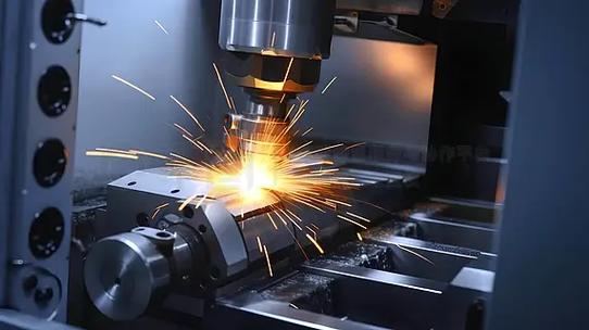
Step 4: Execute the CNC Cutting Process
Once setup is complete, the operator starts the cutting process—either manually (by pressing “Cycle Start” on the machine) or automatically (via a network command).
What Happens During Cutting:
- The CNC controller reads the G-code line by line, sending signals to the servo motors to move the tool or workpiece along the programmed path.
- The spindle (or cutting tool) rotates at the speed set in the CAM program, and the tool moves at the feed rate to remove material.
- Coolant is often sprayed on the tool and workpiece to reduce heat (which can warp the material or damage the tool) and flush away chips (debris from cutting).
Example: When cutting a stainless steel medical implant, the machine would use a coolant mix of water and oil to keep the tool (a tungsten carbide endmill) cool—stainless steel generates high heat during cutting, and overheating would reduce the tool’s lifespan.
Step 5: Post-Cutting Inspection & Finishing
After cutting, the part is removed from the machine and inspected to ensure it meets design standards. Any necessary finishing steps are then performed.
Inspection Tasks:
- Dimensional Checks: Use tools like calipers (for simple measurements), micrometers (for precise thickness checks), or a Coordinate Measuring Machine (CMM) (for complex 3D parts) to verify dimensions against the CAD model.
- Surface Finish Checks: Inspect the part’s surface for roughness (e.g., using a surface roughness tester) or defects (e.g., burrs, scratches).
Finishing Steps (if needed):
- Deburring: Remove sharp edges or small pieces of material (burrs) using a file, sandpaper, or a deburring machine.
- Polishing: For parts that require a smooth surface (e.g., consumer electronics housings), use abrasive pads or chemical polishing.
- Coating: Apply a protective coating (e.g., anodizing for aluminum, powder coating for steel) to improve durability or appearance.
Example: A custom jewelry maker would inspect a CNC-cut brass pendant with a caliper to ensure the pendant’s width is 20mm ±0.05mm, then polish the surface with a fine-grit sandpaper to achieve a shiny finish.
4. Common CNC Cutting Equipment Types
Not all CNC cutting machines are the same—each type is designed for specific materials, thicknesses, and applications. Below are the most widely used options:
|
Equipment Type
|
How It Works
|
Best For
|
|
CNC Milling Machine
|
Uses rotating endmills to cut material (workpiece stays fixed, tool moves).
|
3D parts (e.g., plastic housings, metal brackets) in materials like aluminum, steel, wood.
|
|
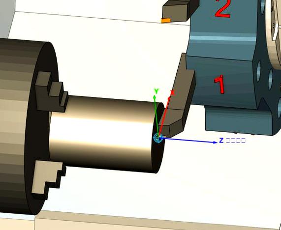
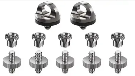
CNC Lathe
|
Rotates the workpiece while a stationary tool cuts it (ideal for cylindrical parts).
|
Round parts (e.g., bolts, shafts, pipes) in metal or plastic.
|
|
CNC Laser Cutter
|
Uses a high-powered laser beam to melt/vaporize material.
|
Thin materials (0.1–20mm) like metal sheets, acrylic, wood, or fabric. Delivers smooth edges.
|
|
CNC Plasma Cutter
|
Uses a plasma arc (superheated gas) to cut through metal.
|
Thick metal (20–100mm) like steel, stainless steel, or aluminum. Fast, but less precise than lasers.
|
|
CNC Waterjet Cutter
|
Uses a high-pressure stream of water (mixed with abrasives) to cut material.
|
Heat-sensitive materials (e.g., glass, stone, titanium) or thick metals (up to 300mm). No heat damage.
|
5. Troubleshooting Common CNC Cutting Issues
Even with proper setup, problems can arise during CNC cutting. Below are solutions to the most frequent issues:
|
Issue
|
Possible Cause
|
Solution
|
|
Cutting surface has burrs
|
Dull tool, low feed rate, or incorrect tool angle.
|
Replace the tool, increase feed rate, or adjust the tool’s cutting angle.
|
|
Part dimensions are off
|
Incorrect work offset, worn servo motors, or thermal expansion.
|
Re-calibrate the work offset, service the motors, or use coolant to reduce heat.
|
|
Tool breaks during cutting
|
Tool is too small for the material, high spindle speed, or loose tool holder.
|
Use a larger-diameter tool, reduce spindle speed, or tighten the tool holder.
|
|
Poor surface finish
|
Vibration (loose workpiece), dull tool, or low spindle speed.
|
Secure the workpiece tighter, replace the tool, or increase spindle speed.
|
6. Conclusion: The Value of CNC Cutting in Modern Manufacturing
CNC cutting is more than just a “fast way to cut material”—it’s a foundational technology that enables precision, scalability, and innovation across industries. By following the step-by-step process outlined here—from CAD design to post-cutting inspection—you can leverage CNC cutting to produce parts that meet strict standards, reduce waste, and save time.
As technology advances, CNC cutting is becoming even more accessible (e.g., desktop CNC machines for small businesses) and intelligent (e.g., AI-powered CAM software that optimizes tool paths automatically). Whether you’re a seasoned manufacturer or a hobbyist, understanding how CNC cutting is done is the first step to unlocking its full potential.
For more insights on CNC machining—including tips for choosing the right machine for your project or optimizing G-code—subscribe to our manufacturing newsletter or contact our team of CNC experts.