Problem Background
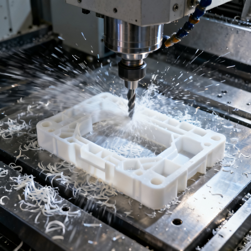
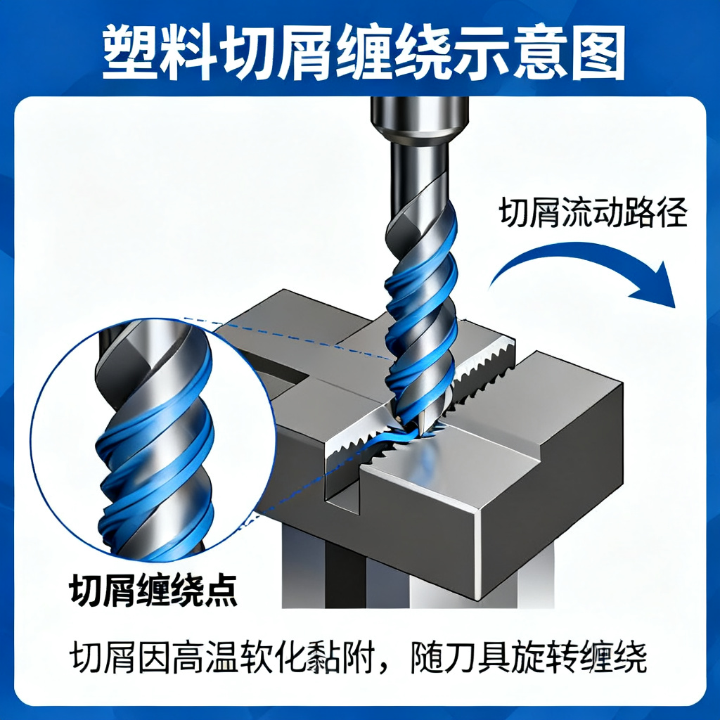
Chip winding is a common and challenging issue in CNC machining of plastic materials. Due to their low thermal conductivity, high ductility, and tendency to melt, plastics often produce continuous long ribbon-shaped chips during cutting. These chips can wrap around tools, workpieces, or machines, significantly impacting machining efficiency and product quality.
I. Analysis of Plastic Material Machining Characteristics
1.1 Physical Properties of Plastic Materials
Compared with metal materials, plastics have significantly different physical properties:
- Low Thermal Conductivity: Thermal conductivity of plastics is only 1/1000 or less than that of metals
- High Ductility: Plastics have good ductility and easily form continuous chips
- High Thermal Expansion Coefficient: 1.5-20 times greater than metals
- Low Elastic Modulus: Only 1/10-1/16 of metals
1.2 Chip Formation Mechanism in Plastics
Plastics mainly form the following chip types during cutting:
- Continuous Chips: Long, continuous strips that are most prone to winding
- Segmented Chips: Chips with smooth bottom and visible cracks on the back
- Granular Chips: Uniform granular chips that are easy to evacuate
- Discontinuous Chips: Irregular fine granular chips
II. Hazards of Chip Winding
2.1 Impact on Machining Quality
- Reduced Surface Quality: Chips scratch workpiece surfaces, affecting surface finish
- Dimensional Accuracy Deviation: Unstable cutting forces caused by chip winding
- Decreased Machining Efficiency: Frequent machine stops required for chip cleaning
2.2 Impact on Equipment and Tools
- Accelerated Tool Wear: Increased friction between chips and tools
- Equipment Damage Risk: Chips entering precision components like machine guideways
- Safety Hazards: High-speed rotating chips may cause personal injury
III. Core Methods for Chip Control
3.1 Tool Parameter Optimization
3.1.1 Tool Geometry Parameters
Rake Angle Selection:
- General plastics: 10°-15°
- Hard plastics: 0°-10°
- Composite materials: -5°-0°
Clearance Angle Selection:
- Roughing: 5°-10°
- Finishing: 10°-25°
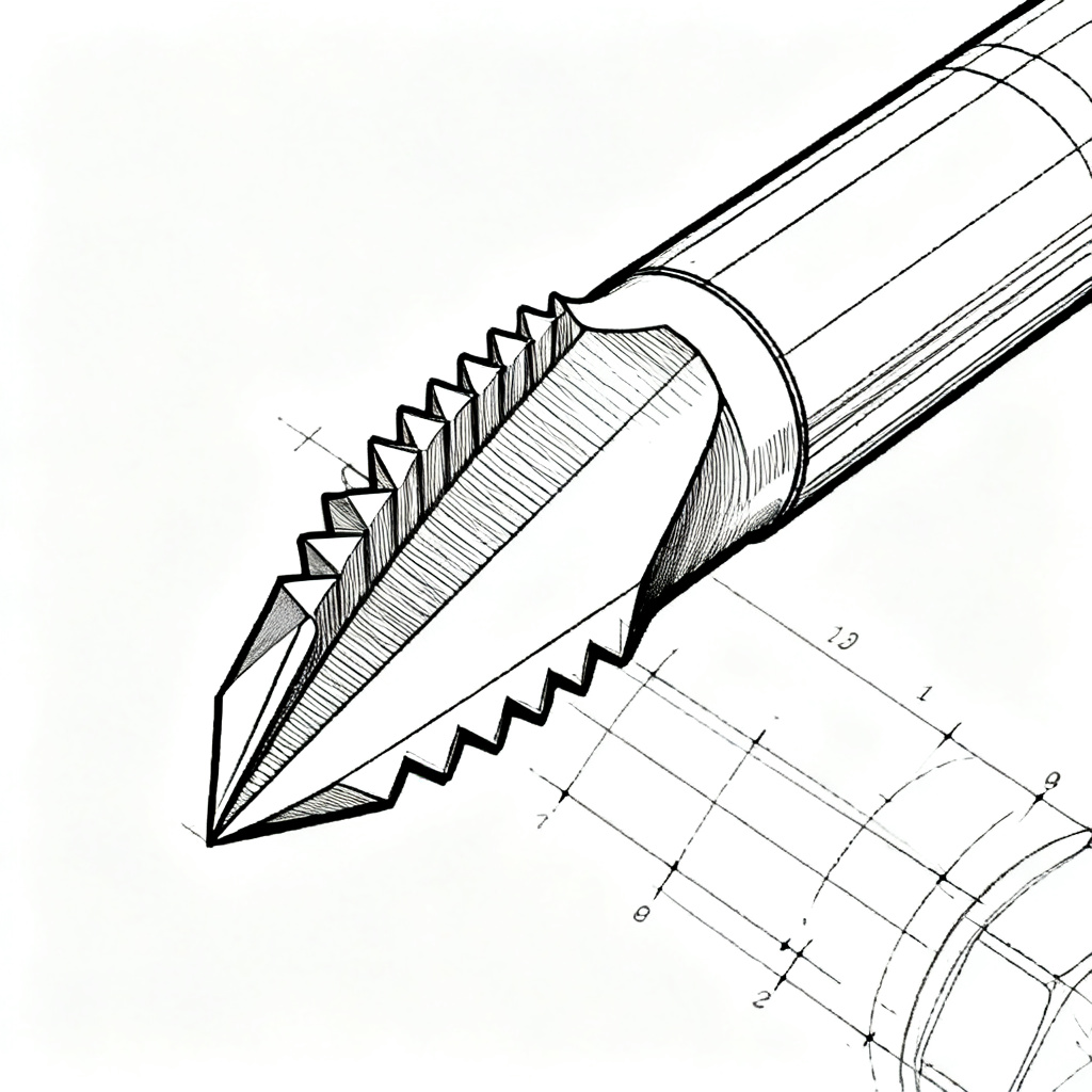
3.1.2 Chip Breaker Design
Chip Breaker Types:
- Linear type: Suitable for carbon steel, alloy steel
- Linear-arc type: Good versatility
- Full arc type: Suitable for high ductility materials
Chip Breaker Width:
- Smaller width results in smaller chip curl radius and easier breaking
- Width must match cutting depth to avoid chip jamming
3.2 Cutting Parameter Adjustment
3.2.1 Cutting Speed Control
Recommended cutting speeds for different plastic materials:
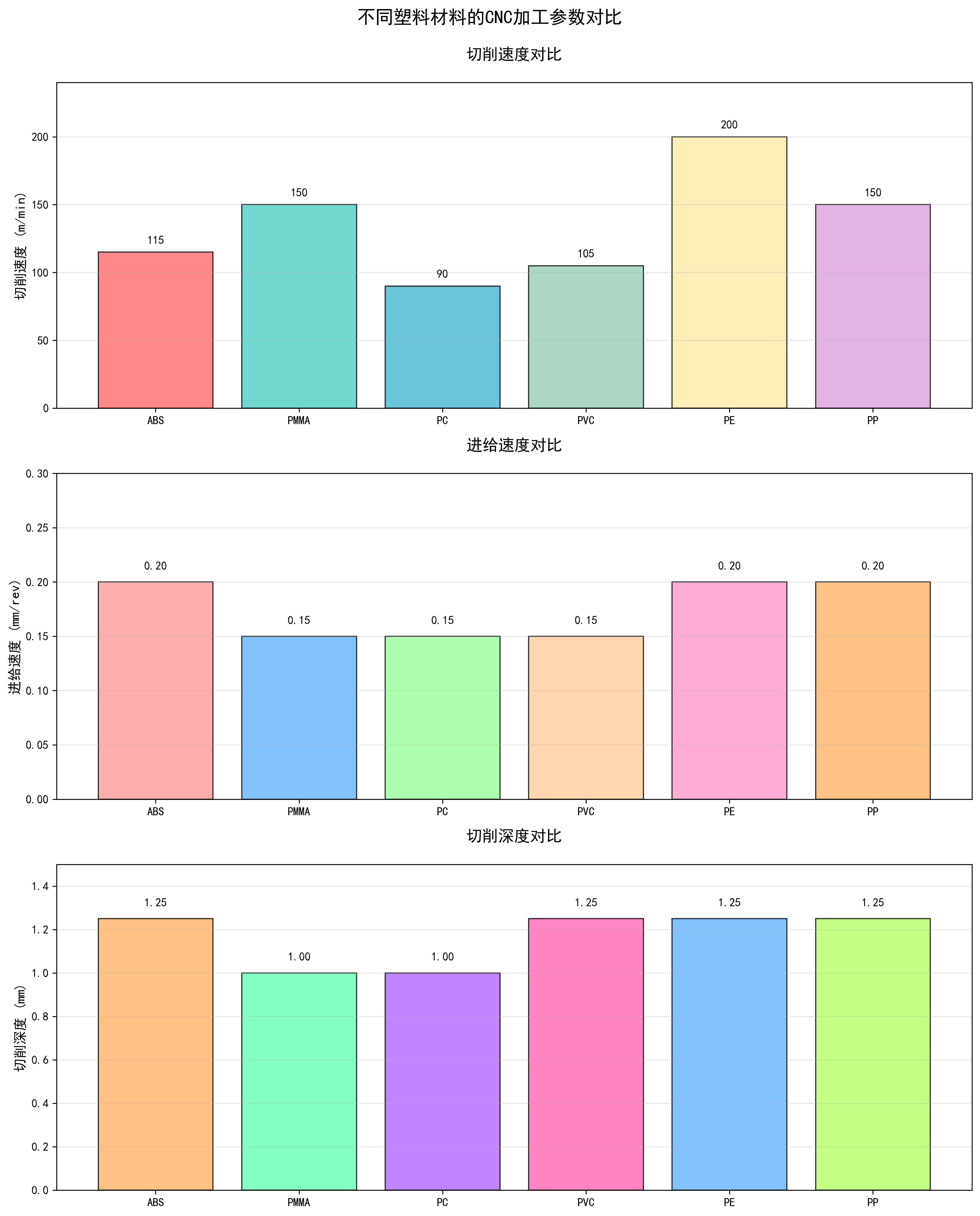
3.2.2 Feed Rate and Depth of Cut
Feed Rate Adjustment Principles:
- Increasing feed rate makes chips thicker and easier to break
- Excessive feed rate increases surface roughness
- Recommended range: 0.1-0.3 mm/rev
Depth of Cut Control:
- Multiple shallow cuts instead of one deep cut
- Recommended range: 0.5-2 mm
- Avoid overheating and material softening
3.3 Cooling and Lubrication Systems
3.3.1 Cooling Method Selection
Gas Cooling:
- Advantages: No workpiece contamination, suitable for high surface requirements
- Common gases: Compressed air, nitrogen
- Application scenarios: Precision machining, easily contaminated materials
Liquid Cooling:
- Advantages: Good cooling effect, can carry away chips
- Common coolants: Water-soluble coolants, oil mist
- Considerations: Avoid chemical reactions with plastics
3.3.2 Cooling Parameter Settings
Coolant Pressure:
- General machining: 0.3-0.5 MPa
- Deep hole machining: 1-2 MPa
- High-pressure cooling: 5-10 MPa
Coolant Flow Rate:
- Adjust based on tool diameter
- Ensure coolant covers entire cutting area
3.4 Chip Breaking Tool Holder Technology
3.4.1 Working Principle
Chip breaking tool holders use low-frequency vibration technology to make tools perform precise, controlled low-frequency micro-vibrations along the spindle direction, forming sinusoidal cutting trajectories.
Technical Features:
- Periodically creates “vibration gaps” with brief separation between tool and workpiece
- Chips break at preset lengths, forming fan-shaped granular chips
- Also provides heat dissipation, reducing material softening
3.4.2 Application Effects
- Chip Control: Effectively prevents chip winding
- Heat Dissipation: Reduces cutting temperature by over 30%
- Surface Quality: Improves Ra value by 20%-50%
- Machining Efficiency: Reduces downtime for chip cleaning by over 80%
IV. Chip Control Strategies for Different Plastic Materials
4.1 Thermoplastics
ABS Plastic:
- Cutting speed: 80-150 m/min
- Feed rate: 0.1-0.3 mm/rev
- Characteristics: Easily produces continuous chips, requires enhanced chip breaking measures
PP Plastic:
- Cutting speed: 100-200 m/min
- Feed rate: 0.1-0.3 mm/rev
- Characteristics: Good flexibility, chips easily wind, requires sharp tools
4.2 Engineering Plastics
POM (Polyoxymethylene):
- Cutting speed: 120-180 m/min
- Feed rate: 0.1-0.25 mm/rev
- Characteristics: High hardness, causes significant tool wear, requires wear-resistant tools
PC (Polycarbonate):
- Cutting speed: 60-120 m/min
- Feed rate: 0.1-0.2 mm/rev
- Characteristics: Poor heat resistance, easily melts, requires adequate cooling
4.3 Composite Materials
Fiberglass Reinforced Plastic:
- Cutting speed: Lower range, 30-60 m/min
- Feed rate: 0.05-0.15 mm/rev
- Characteristics: Alternating hard and soft phases, rapid tool wear, requires diamond tools
Carbon Fiber Composite:
- Cutting speed: 30-50 m/min
- Feed rate: 0.05-0.1 mm/rev
- Characteristics: High cutting forces, requires special tools and processes
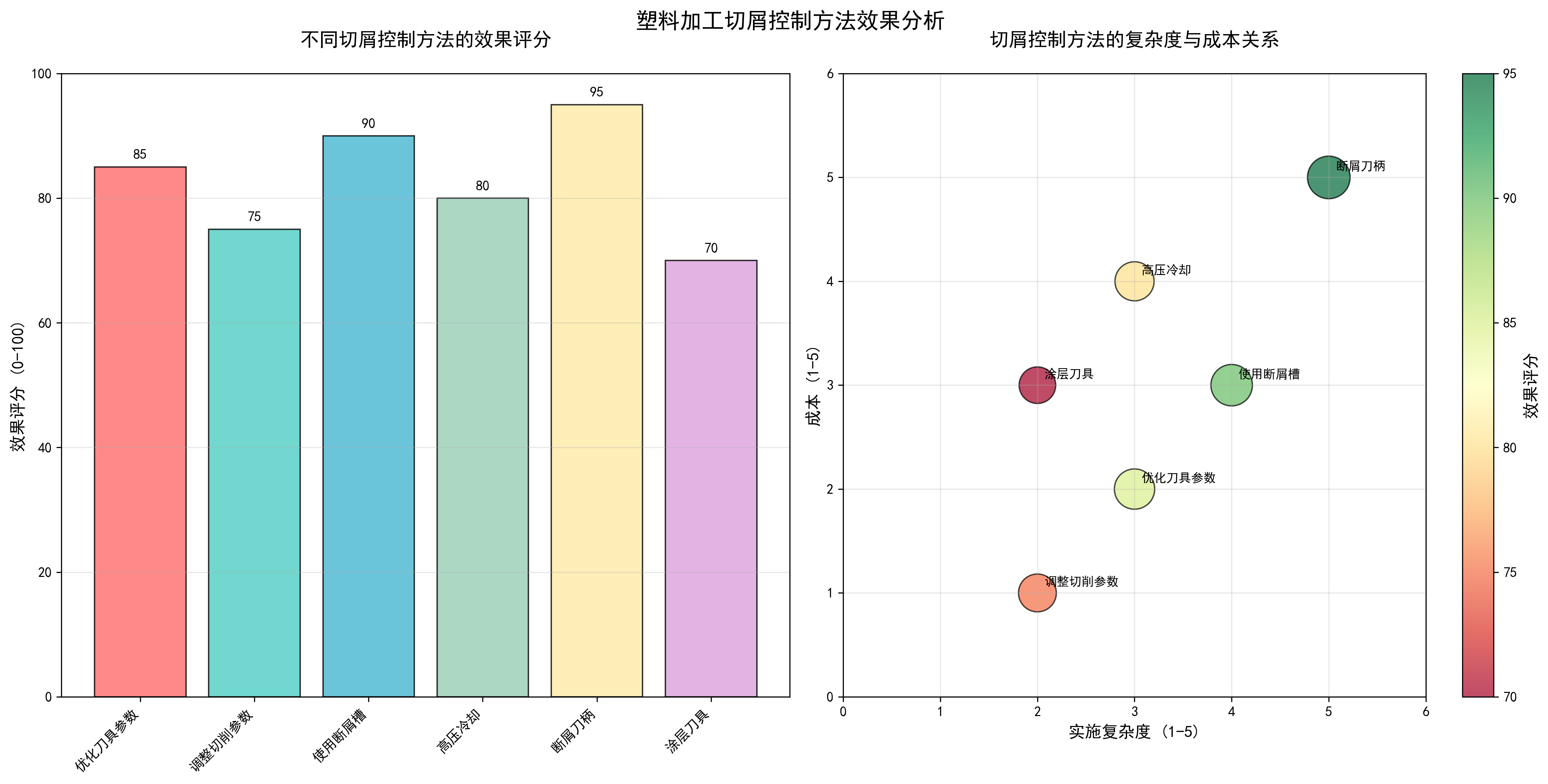
V. Chip Control Effect Evaluation
5.1 Evaluation Metrics
Chip Morphology Evaluation:
- Ideal: Granular or short segmented
- Acceptable: C-shaped or 6-shaped
- Unacceptable: Long continuous or wound
Machining Quality Evaluation:
- Surface roughness Ra value
- Dimensional accuracy deviation
- Machining efficiency improvement ratio
5.2 Effect Comparison of Different Control Methods
VI. Practical Procedures and Considerations
6.1 Implementation Steps for Chip Control
Step 1: Material Property Analysis
- Identify plastic material type and characteristics
- Analyze material thermal sensitivity and ductility
- Develop targeted control strategies
Step 2: Tool Selection and Optimization
- Choose appropriate tool material based on workpiece material
- Optimize tool geometry parameters (rake angle, clearance angle, chip breaker)
- Ensure tool sharpness and coating quality
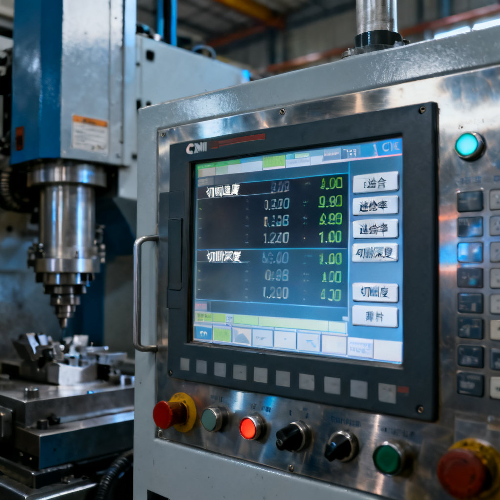
Step 3: Cutting Parameter Setup
- Set initial parameters based on recommended parameter tables
- Fine-tune based on actual machining conditions
- Establish parameter database
Step 4: Cooling System Configuration
- Select appropriate cooling method
- Adjust coolant pressure and flow rate
- Ensure cooling effect covers cutting area
Step 5: Machining Process Monitoring
- Real-time observation of chip morphology
- Monitor machining sounds and vibrations
- Regularly check tool wear conditions
6.2 Considerations
Safety Considerations
- Wear safety glasses and gloves
- Ensure machine safety guards are intact
- Regularly clean chips to prevent accumulation
Quality Control Considerations
- First article inspection to confirm parameter appropriateness
- Regularly check machined surface quality
- Establish quality traceability system
Equipment Maintenance Considerations
- Regularly clean chip collection system
- Check cooling system operating status
- Maintain machine accuracy and rigidity
VII. Case Studies
7.1 Success Case: Automotive Plastic Component Machining
Problem Description:
An automotive component manufacturer faced severe chip winding issues when machining PP plastic interior parts, resulting in low efficiency and 15% scrap rate.
Solution:
- Tool Optimization: Used carbide tools with special chip breakers
- Parameter Adjustment: Cutting speed 180 m/min, feed rate 0.25 mm/rev
- Cooling System: High-pressure air cooling at 0.6 MPa
- Machining Strategy: Layered milling with 0.8 mm depth per cut
Implementation Results:
- Chip morphology improvement: From long continuous to short segmented
- Machining efficiency increase: 40% improvement
- Scrap rate reduction: From 15% to below 3%
7.2 Failure Case Analysis
Problem Description:
An electronic device manufacturer experienced high scrap rates due to poor chip control when machining PC plastic housings.
Failure Causes:
- Inappropriate Tool Selection: Used regular HSS tools with poor wear resistance
- Unreasonable Parameter Settings: Excessive cutting speed (250 m/min)
- Inadequate Cooling: Only low-pressure coolant used
- Poor Machining Strategy: Single deep cut (3 mm)
Improvement Measures:
- Changed to PCD diamond-coated tools
- Reduced cutting speed to 120 m/min
- Increased cooling pressure to 1 MPa
- Changed to layered machining with 1 mm depth per cut
VIII. Summary and Future Outlook
8.1 Key Points Summary
- Material Properties are Fundamental: Fully understand physical characteristics of plastic materials
- Tool Optimization is Critical: Proper selection of tool materials and geometry parameters
- Parameter Matching is Core: Optimal combination of cutting speed, feed rate, and depth of cut
- Cooling System is Essential: Effective control of cutting temperature
- Process Monitoring is Method: Real-time adjustment of machining parameters
8.2 Technology Development Trends
Intelligent Chip Control:
- Real-time chip morphology monitoring using machine vision
- Adaptive control algorithms for automatic parameter adjustment
- AI optimization of cutting strategies
Advanced Tool Technologies:
- Widespread application of nano-coated tools
- 3D printed customized tools
- Development of smart tools
Green Machining Technologies:
- Promotion of dry cutting technology
- Application of environmentally friendly coolants
- Chip recycling and reuse technologies
8.3 Recommendations and Outlook
For effective chip control in CNC plastic machining, we recommend focusing on:
- Establish Material Database: Collect machining characteristic data for different plastics
- Optimize Process Parameters: Develop standardized processes based on material characteristics
- Enhance Personnel Training: Improve operator technical skills
- Adopt Advanced Technologies: Implement intelligent equipment and monitoring systems
- Continuous Improvement: Establish PDCA cycle improvement mechanism
Through scientific chip control methods, we can significantly improve plastic machining efficiency and quality, reduce production costs, and provide technical support for manufacturing transformation and upgrading.
References:
- “Plastic Cutting Technology”
- “CNC Machining Parameter Optimization Guide”
- “Modern Cutting Technology Handbook”
- “Engineering Plastics Processing Technology”
Technical Consultation:
For further technical consultation, please contact professional CNC machining technology service providers for personalized solutions.
Disclaimer
All experimental data presented in this paper are derived from controlled production environments and standardized test procedures. However, due to differences in equipment models, material batches, and on-site operating conditions, readers are advised to verify and adjust technical parameters according to their specific application scenarios before practical implementation.
The research results and technical insights shared herein are based on the author’s professional experience and experimental observations. The author and the affiliated institution shall not be liable for any direct, indirect, or consequential damages (including but not limited to equipment damage, product quality issues, or production losses) arising from the improper use of the information provided in this paper.