Answer
When designing CNC – machined parts, one should follow the principles of “manufacturability, precision adaptation, and cost control”. The process includes requirements analysis → 3D modeling → process planning → parameter optimization → simulation verification, and CAD/CAM software such as UG and SolidWorks are used to complete the design and tool – path planning.
Extended Answer
I. Requirements Analysis and Determination of Technical Parameters
Clarify Functional Requirements
Determine the purpose of the part. For example, for load – bearing parts (such as a mechanical support, the direction and magnitude of the force need to be clarified), motion characteristics (such as a slider requires ensuring straightness), and environmental requirements (such as high – temperature or corrosive environments).
Case: When designing a connecting rod for an automobile engine, it needs to meet the fatigue strength under high – speed rotation. The material selected is 40Cr alloy steel with a tensile strength of ≥ 980MPa.
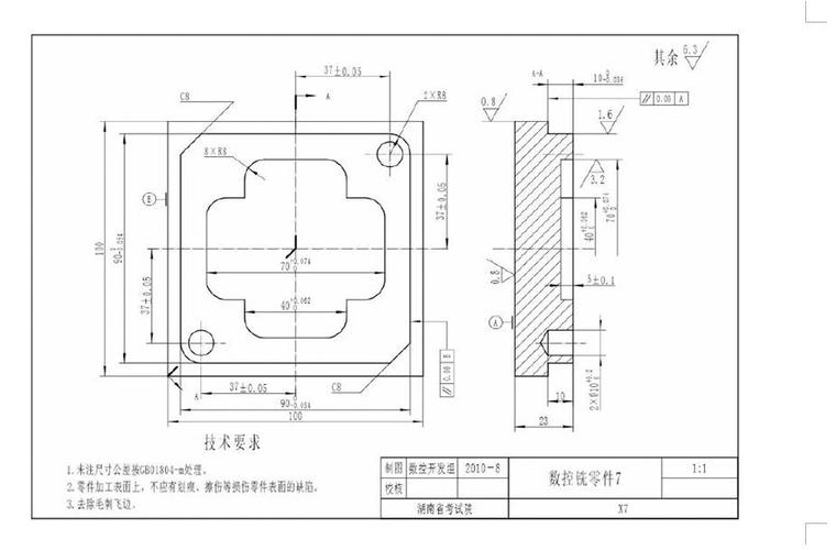
Set Dimensions and Precision
Determine the key dimensions according to the assembly relationship and mark the tolerances (such as H7/g6 for hole – shaft fit).
Precision classification:
General level (±0.1mm): Suitable for non – mating surfaces;
Precision level (±0.01mm): Used for bearing holes and guide grooves;
Ultra – precision level (±0.001mm): Such as the mounting seat for optical lenses.
Material Selection
Select materials based on functions. For example, aluminum alloy (6061) is used for lightweight structures, and stainless steel (304) is used for corrosion – resistant components.
Consider the cutting performance of materials. For example, titanium alloy has a large cutting force and requires special tools and cooling strategies.
II. 3D Modeling and Design Optimization
Use Professional Design Software
Mainstream tools: SolidWorks (user – friendly, suitable for mechanical parts), UG NX (comprehensive functions, often used in automotive molds), CATIA (dominant in the aerospace field).
Operation process: Sketch drawing → Feature modeling (extrusion, rotation, scanning) → Assembly verification.
Design Principles
Avoid sharp corners and deep cavities: Sharp corners are likely to cause tool chipping, and deep cavities (depth > 5 times the diameter) require long tools, which are prone to vibration;
Simplify the structure: Reduce unnecessary curved surfaces and undercuts. For example, split complex curved surfaces into multiple planar splicings;
Fillet transition: Add fillets with R≥0.5mm at corners to improve tool life.
Assembly Compatibility Check
Verify the fit of the part with other components through virtual assembly to avoid interference. For example, check the meshing clearance of gears in a gearbox.
III. Process Planning and Tool Selection
Determine the Machining Process
Rough machining: Prioritize milling or turning with large depth – of – cut and high feed to remove most of the stock;
Finish machining: Use small depth – of – cut and low feed to ensure surface roughness (such as Ra≤0.8μm);
Special processes: Use gun drills for deep holes (L/D > 5), and vibration cutting for thin – walled parts to reduce deformation.
Tool Selection
Type selection: End mills are used for plane and contour machining, ball – nose mills for curved surfaces, and drills / reamers for hole machining;
Size matching: The tool diameter should be smaller than the groove width or hole diameter. For example, when machining a 5mm – wide groove, select a 4mm end mill to leave a margin.
Clamping Scheme Design
Select fixtures according to the shape of the part: parallel vice (for regular shapes), magnetic worktable (for magnetic materials), and special fixtures (for complex curved surfaces);
Follow the “six – point positioning” principle to ensure the stability of the workpiece. For example, set positioning pins on the bottom and side of the part.
IV. Optimization of Cutting Parameters and Programming
Determination of Cutting Parameters
Spindle speed (S): Adjust according to the material and tool diameter. For example, when using a Φ10mm carbide tool for aluminum alloy, S = 2000 – 3000rpm;
Feed rate (F): F = 300 – 800mm/min for rough machining and F = 50 – 200mm/min for finish machining;
Depth of cut (ap): ap = 1/3 – 1/2 of the tool diameter for rough machining, and ≤ 0.5mm for finish machining.
Tool – path Planning
Strategy selection: Conventional milling (smooth surface, suitable for finish machining), climb milling (impact – resistant, suitable for rough machining);
Path optimization: Reduce idle strokes, use helical plunge instead of vertical plunge to avoid the tool directly hitting the workpiece.
Programming and Simulation
Automatically generate G – code using CAM software such as Mastercam or Powermill;
Verify the tool – path through software simulation or the virtual system of the machine tool to check for over – cutting and tool – collision risks.
V. Manufacturability Assessment and Cost Control
Manufacturing Feasibility Analysis
Check whether the design exceeds the capabilities of the equipment. For example, complex curved surfaces that can only be processed by a five – axis machine tool cannot be achieved by an ordinary three – axis machine tool;
Evaluate processing time and cost. For example, deep – hole machining is costly, and changing it to a stepped hole can reduce the difficulty.
Cost – Optimization Strategies
Material utilization: Optimize the nesting scheme, such as using nesting cutting to reduce waste;
Process simplification: Combine processes, such as integrating drilling and tapping into the same step;
Standardized design: Use standard parts (such as bolts and nuts) instead of custom – made parts to reduce costs.
VI. Design Verification and Iteration
Prototype Production and Testing
Produce the first – piece sample, and use a coordinate measuring machine (CMM) to detect the key dimensions. If the error exceeds the tolerance, the design needs to be adjusted;
Conduct functional tests. For example, a sealing part needs to pass an air – tight test to verify the effectiveness of the design.
Design Iteration
Modify the model according to the test results and regenerate the program;
Establish design documents to record the modification process, providing a reference for subsequent optimization.
Extension: The Impact of Emerging Technologies on CNC Design
Topology optimization: Use software such as ANSYS to generate lightweight structures, reducing material waste;
Hybrid manufacturing: Combine 3D printing and CNC. First, print complex shapes, and then use milling to ensure precision;
Intelligent design: AI – assisted recommendation of cutting parameters and prediction of tool life to improve design efficiency.
Through a systematic design process, CNC – machined parts can meet functional requirements while taking into account processing efficiency and cost, and are widely used in aerospace, automotive manufacturing, mold processing, and other fields.