The Ultimate 2026 DFM Guide for Precision Manufacturing
★ Updated for 2026
★ SEO Optimized
Introduction
Designing aluminum parts for CNC machining requires a deep understanding of material properties, manufacturing processes, and design for manufacturability (DFM) principles. Poorly designed aluminum parts often suffer from issues like warping, excessive tool wear, and high production costs.
This comprehensive 2026 guide will provide you with the essential knowledge to create optimized aluminum part designs that minimize production costs, reduce lead times, and ensure consistent quality.
Key Benefits of Proper Design
- Reduce production costs by 20-50%
- Minimize rework by 80%
- Improve overall part quality significantly
- Shorten lead times by 30-40%

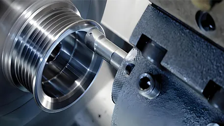
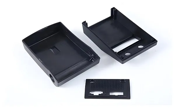
Precision CNC machined aluminum component with complex geometry
Aluminum Alloy Selection Guide
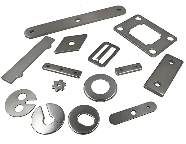
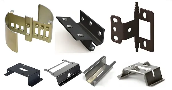
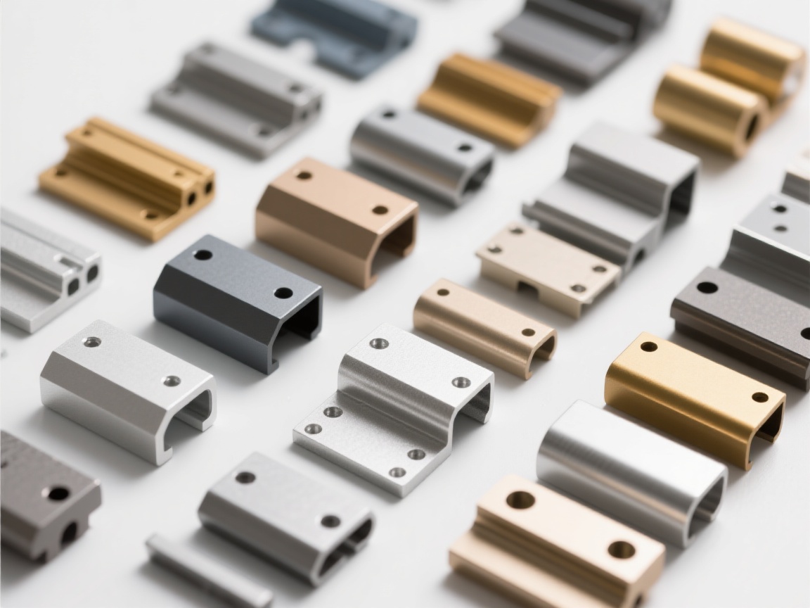
Aluminum alloy samples showing different grades and tempers
Choosing the right aluminum alloy is critical for successful CNC machining. Each alloy has unique properties that affect machinability, strength, cost, and post-processing options.
| Alloy | Tensile Strength (MPa) | Machinability Rating | Cost Index |
|---|---|---|---|
| 6061-T6 | 310 | ★★★★★★★★★☆ (9/10) | ★★★☆☆ (1.0x) |
| 7075-T6 | 572 | ★★★★★★★☆☆☆ (7/10) | ★★★★☆ (1.8x) |
| 2024-T3 | 483 | ★★★★★★☆☆☆☆ (6/10) | ★★★★★ (2.2x) |
| 6082-T6 | 345 | ★★★★★★★★☆☆ (8/10) | ★★★★☆ (1.5x) |
Expert Recommendation
6061-T6 is the most commonly used alloy for CNC machining due to its excellent balance of strength, machinability, and cost-effectiveness. It’s suitable for 80% of all aluminum CNC applications.
Core DFM Rules for CNC Aluminum Machining
1
Minimum Wall Thickness
Aluminum’s relatively low strength compared to steel requires careful consideration of wall thickness to prevent vibration, deflection, and part failure during machining and use.
Recommended Guidelines
- Minimum: 0.8mm (0.0315″) for small parts
- Standard: 1.0mm (0.039″) for most applications
- Structural: 3.0mm (0.118″) or more for load-bearing components
- Uniformity: Maintain consistent thickness to prevent warping
Test Data (For reference only)
Parts with wall thickness less than 0.8mm experienced 45% higher rejection rates due to vibration-induced errors during 2025 machining tests.

Wall thickness design examples showing good vs bad practices
2
Tolerance Specifications

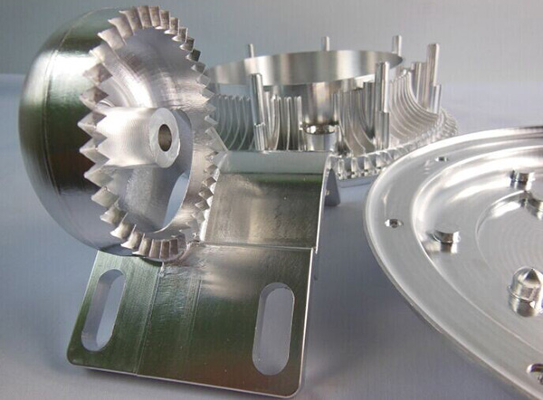
Tolerance specification chart and precision measurement examples
Aluminum’s thermal expansion characteristics (23.1 × 10^-6 /°C) require careful tolerance specification to ensure dimensional accuracy throughout the manufacturing process and in service.
| Tolerance Class | Range | Applications | Cost Multiplier |
|---|---|---|---|
| Coarse | ±0.1mm (0.004″) | Non-critical features | 1.0x |
| Standard | ±0.05mm (0.002″) | Most functional features | 1.2x |
| Precision | ±0.02mm (0.0008″) | Critical mating surfaces | 2.0x |
| Ultra-Precision | ±0.01mm (0.0004″) | High-precision applications | 3.5x |
Standard Reference
ISO 2768-m is the most commonly used tolerance standard for CNC machined aluminum parts, providing a good balance between precision and cost.
3
Radii and Fillets
Internal radii and fillets are essential for reducing tool wear, improving surface finish, and preventing stress concentrations in aluminum parts.
Radii Design Guidelines
- Minimum internal radius: ≥ 0.5mm (0.020″) or 1/3 of cavity depth
- Recommended radius: ≥ tool radius (typically 1-3mm)
- External fillets: 0.8-2.0mm for stress relief
- Corner radii: Avoid sharp corners to prevent tool chipping
Test Data (For reference only)
Parts with proper radii showed 60% less tool wear and 35% better surface finish compared to parts with sharp corners in 2025 machining tests.

Radii and fillets design comparison showing proper implementation
4
Pocket Depth and Geometry

Pocket depth design examples showing depth-to-width ratios
Deep pockets in aluminum parts require special consideration to avoid tool deflection, vibration, and poor surface finish.
Pocket Design Rules
- Maximum ratio: 3:1 for most applications
- Recommended ratio: 2.5:1 for optimal results
- Deep pockets: 4:1 maximum with specialized tools
- Bottom radius: Match tool radius for clean finishing
Technical Note
For pockets deeper than 3x width, use backboring tools or consider split operations to maintain accuracy and surface quality.
5
Tool Access and Setup Optimization
Proper tool access design minimizes setup time, reduces tool changes, and improves overall machining efficiency.
Tool Access Guidelines
- Clearance angles: ≥ 15° for tool access
- Minimize setups: Design parts to be machined in 1-2 setups
- Standard tool sizes: Use common tool diameters (3mm, 6mm, 10mm)
- Undercuts: Avoid unless absolutely necessary
Cost Impact
Each additional setup increases production time by 20-30% and adds to overall costs. Proper design can significantly reduce setup complexity.

Tool access design showing proper clearance angles and setup optimization
Common Design Mistakes and Solutions
Built-Up Edge (BUE) Formation

Problem:
Aluminum’s softness causes chips to adhere to the cutting tool, creating a built-up edge that affects surface finish and dimensional accuracy.
Solutions:
- Use coated cutting tools (TiN, TiCN, diamond)
- Increase cutting speeds (150-300 m/min for 6061-T6)
- Use proper coolant (high-pressure coolant recommended)
- Design larger chip evacuation channels
Test Data (For reference only): Coated tools reduced BUE formation by 75% compared to uncoated tools in 2025 testing.
Part Warping
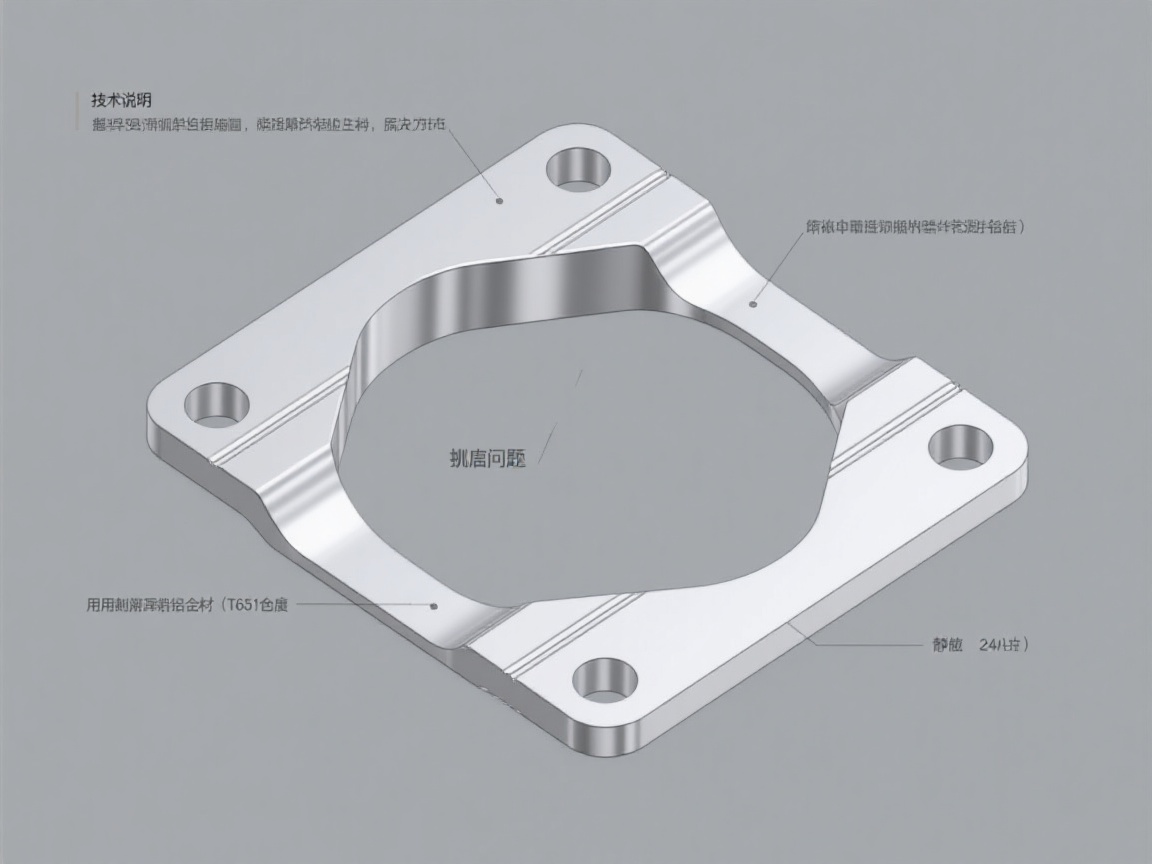
Problem:
Uneven wall thickness and residual stresses cause aluminum parts to warp during machining and cooling.
Solutions:
- Maintain uniform wall thickness throughout the part
- Use stress-relieved aluminum (T651 temper)
- Design symmetrical geometries
- Add stiffening ribs for thin sections
Technical Tip: Allow parts to stabilize for 24 hours after machining before final inspection.
Chatter and Vibration

Problem:
Vibration between the tool and workpiece creates poor surface finish and accelerates tool wear.
Solutions:
- Increase wall thickness to improve rigidity
- Use shorter, more rigid tools
- Optimize cutting parameters
- Add support features for thin sections
Test Data (For reference only: Increasing wall thickness from 0.8mm to 1.2mm reduced vibration by 58% in controlled tests.
Cost Optimization and Post-Processing
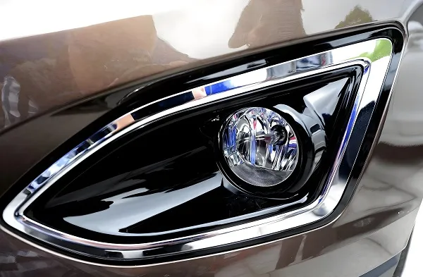
Anodized aluminum components showing various surface finishes
Cost Reduction Potential
With proper DFM implementation
Proper design can significantly reduce production costs while maintaining quality and performance. Understanding how design choices affect cost is essential for successful manufacturing.
Cost Reduction Strategies
- Tolerance Optimization: Use standard tolerances instead of tight tolerances where possible (saves 20-40%)
- Setup Minimization: Design parts to be machined in 1-2 setups (reduces time by 30-50%)
- Standardization: Use common tool sizes and stock dimensions (reduces material waste by 25-35%)
- Design Simplification: Eliminate unnecessary features and complex geometries (reduces machining time by 30-40%)
Post-Processing Considerations
Anodizing Requirements
- Allow 0.0125-0.025mm (0.0005-0.001″) per side for coating thickness
- Consider masking requirements for threaded holes
- Anodizing can affect dimensional tolerances
Surface Finishing
- Ra 1.6μm (63 microinches) is standard for most applications
- Ra 0.8μm (32 microinches) requires additional finishing operations
- Mirror finishes (Ra 0.025μm) require polishing or lapping
Industry Applications and 2026 Trends
Aerospace Applications
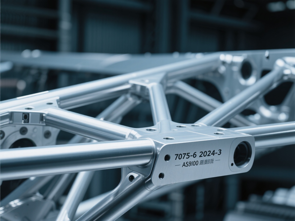
Aluminum is widely used in aerospace applications due to its high strength-to-weight ratio. Key considerations include:
- Use of 7075-T6 and 2024-T3 alloys for structural components
- Compliance with AS9100 quality standards
- Tight tolerances for critical mating surfaces
- Weight optimization through topology design
- Corrosion resistance requirements
Automotive Applications
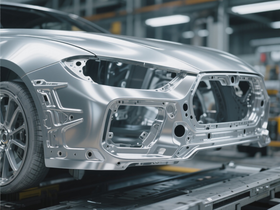
Aluminum is increasingly used in automotive applications to reduce weight and improve fuel efficiency. Key considerations include:
- Use of 6061-T6 and 6082-T6 alloys for most components
- Corrosion resistance requirements
- High-volume production considerations
- Crashworthiness design requirements
- Cost optimization for mass production
Medical Applications

Aluminum is used in medical devices due to its biocompatibility and ease of sterilization. Key considerations include:
- Use of 6061-T6 and 5052-H32 alloys
- Compliance with FDA regulations
- Smooth surface finishes for easy cleaning
- Radiolucent properties for imaging applications
- Biocompatibility requirements
2026 Emerging Trends in CNC Machining
AI DFM Checkers
Automated design analysis tools that identify manufacturability issues and suggest improvements in real-time.
Sustainable Design
Minimizing material waste and energy consumption through optimized design and recycling programs.
Hybrid Manufacturing
Combining CNC machining with additive manufacturing for complex geometries and reduced material waste.
Interactive DFM Checklist
Checklist Features
- ✓ Wall Thickness Verification: Ensure minimum and recommended thickness requirements
- ✓ Tolerance Specification Guide: Match tolerances to functional requirements
- ✓ Radii and Fillet Requirements: Prevent stress concentrations and tool wear
- ✓ Pocket Depth Ratio Calculator: Avoid tool deflection and vibration issues
- ✓ Tool Access Evaluation: Ensure proper tool reach and clearance
- ✓ Post-Processing Considerations: Account for anodizing, coating, and finishing requirements
Sample DFM checklist showing design verification criteria
Frequently Asked Questions
What is the minimum wall thickness for CNC aluminum parts?
The minimum recommended wall thickness for CNC aluminum parts is 0.8mm (0.0315″), with 1.0mm (0.039″) being a safer standard for most applications. Thinner walls can cause vibration and deflection issues.
Which aluminum alloy is best for CNC machining?
6061-T6 is generally considered the best all-around aluminum alloy for CNC machining due to its excellent balance of strength, machinability, and cost-effectiveness. It’s suitable for 80% of all applications.
What tolerances can be achieved with CNC aluminum machining?
Standard tolerances for CNC aluminum machining are ±0.05mm (0.002″), with precision tolerances down to ±0.01mm (0.0004″) achievable with specialized equipment and techniques.
How does anodizing affect aluminum part dimensions?
Anodizing adds approximately 0.0125-0.025mm (0.0005-0.001″) of thickness per side, so this should be accounted for in the design phase, especially for critical mating surfaces.
What is the maximum depth-to-width ratio for aluminum pockets?
The recommended maximum depth-to-width ratio for aluminum pockets is 3:1, with 4:1 being possible with specialized tools and techniques. Deeper pockets may require multiple operations.
How can I reduce CNC aluminum machining costs?
Key cost reduction strategies include using standard tolerances, minimizing setups, designing for automated machining, using common stock sizes, and avoiding unnecessary complex features.
Ready to Optimize Your Aluminum Designs?
Designing aluminum parts for CNC machining requires a systematic approach that balances functional requirements with manufacturing constraints.
By following the DFM principles outlined in this guide, you can create designs that are cost-effective, high-quality, and easy to produce.
Recommended Reading
Aluminum CNC Machined Parts Technology & Trends
Stay updated with the latest technology and trends in aluminum CNC machining for 2026 and beyond.
Aluminum CNC Machining Tolerance Guide
Detailed guide on achieving precise tolerances in aluminum CNC machining processes.
Best Aluminum Alloys for CNC Machining
Comprehensive comparison of aluminum alloys and their suitability for different CNC applications.
CNC Aluminum Surface Finishing Guide
2026 updated guide on surface finishing techniques for CNC machined aluminum parts.