CNC programming involves creating a set of instructions (G-code/M-code) that guide a CNC machine to produce a part. The process follows a structured workflow, from understanding the part design to validating the program. Here’s a step-by-step breakdown:
Step 1: Understand the part design and requirements
Before writing code, analyze the part’s technical drawing or 3D model (from CAD software like SolidWorks or Fusion 360). Key details to note:
- Dimensions and tolerances: Critical measurements (e.g., hole diameters, surface finishes) and allowable errors (e.g., ±0.001 inches).
- Material: Properties like hardness (e.g., aluminum vs. steel) affect tool selection and cutting parameters (speed, feed rate).
- Machining operations needed: Identify processes like milling, drilling, or turning required to shape the part.
Example: A steel bracket with a 0.5-inch diameter hole, 2-inch length, and a 30° chamfer on one edge will require drilling, facing, and chamfering operations.
Step 2: Choose the right CNC programming method
Select a programming approach based on complexity and experience:
- Manual programming: Write G-code/M-code directly (using a text editor or CNC controller panel) for simple parts (e.g., straight cuts, basic holes). Best for beginners learning code logic.
- CAM software: Use Computer-Aided Manufacturing tools (e.g., Mastercam, Fusion 360) to automate code generation for complex parts (e.g., 3D contours, multi-axis cuts). The software converts CAD models into toolpaths and G-code.
For most users, CAM software is preferred for efficiency, but learning manual programming builds foundational knowledge.
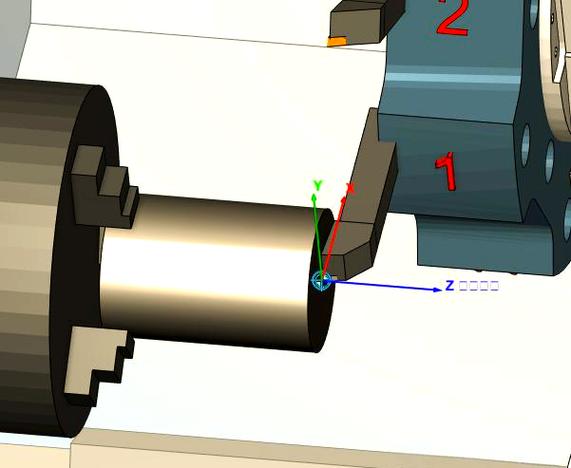
Step 3: Define work offsets and coordinate system
Set the reference point (origin) for the machine’s axes to ensure the tool aligns with the workpiece:
- Work offsets (e.g., G54-G59): These codes tell the machine where the workpiece is located relative to the machine’s “home” position. Measure the distance from the machine’s home to the workpiece’s edge (using a probe or edge finder) and input these values into the controller.
- Axis orientation: Confirm the coordinate system (e.g., X=horizontal, Y=horizontal, Z=vertical for milling; X=axial, Z=radial for turning) matches the machine’s configuration.
Step 4: Select tools and define cutting parameters
Choose appropriate cutting tools and set parameters based on the material and operation:
- Tool selection: Use end mills for milling, drills for holes, or turning inserts for lathes. Note the tool’s diameter, length, and material (e.g., carbide for hard metals).
- Cutting parameters:
-
- Spindle speed (RPM): Calculated based on tool diameter and material (e.g., 1000 RPM for a 0.5-inch carbide end mill in aluminum).
-
- Feed rate (in/min): Determines how fast the tool moves during cutting (e.g., 50 in/min for roughing steel).
-
- Depth of cut: How much material is removed per pass (e.g., 0.1 inches for aluminum to avoid tool overload).
These values are often sourced from tool manufacturer charts or CAM software databases.
Step 5: Write or generate the program (G-code/M-code)
For manual programming (simple parts):
Use standard G-codes (geometric commands) and M-codes (miscellaneous commands) to outline toolpaths. Basic structure:
- Start with setup codes:
-
- G21 (use metric units) or G20 (imperial units).
-
- G17 (select X-Y plane for milling) or G18 (X-Z plane for turning).
-
- G54 (activate work offset).
- Define tool change: T1 M6 (select Tool 1 and change it).
- Set spindle and feed: S1000 M3 (spindle on clockwise at 1000 RPM); F50 (feed rate 50 in/min).
- Program toolpaths:
-
- G00 X0 Y0 Z0.1 (rapid move to X=0, Y=0, Z=0.1 above the workpiece).
-
- G01 Z-0.1 F10 (feed down to 0.1 inches deep).
-
- G01 X2.0 (cut linearly to X=2.0).
- End with cleanup codes: M05 (spindle off); M30 (program end, reset to start).
For CAM software (complex parts):
Import the 3D CAD model, then:
- Define the workpiece boundary and stock size.
- Select machining operations (e.g., “face mill” for flat surfaces, “drill” for holes).
- Assign tools and parameters (software auto-fills recommendations based on material).
- Generate toolpaths, then post-process to convert them into machine-specific G-code (using a post-processor matched to the CNC brand, e.g., Fanuc or Haas).
Step 6: Validate and simulate the program
Before running the program on the machine:
- Check for errors: Use the CNC controller’s edit mode to scan for invalid codes (e.g., typos in G02 instead of G01) or impossible movements (e.g., tool crashing into the workpiece).
- Simulate: Use CAM software or the machine’s built-in simulator to visualize the toolpath. Ensure no collisions occur between the tool, workpiece, or machine components (e.g., spindle, 夹具).
- Test with dry run: Run the program without cutting (tool raised 0.1 inches above the workpiece) to verify movement directions and speeds.
Step 7: Transfer and run the program
- Load the program: Transfer G-code to the CNC controller via USB, network, or SD card.
- Set up the machine: Clamp the workpiece, load tools, and confirm work offsets.
- Execute: Start the program and monitor the first cycle. Pause immediately if anomalies (e.g., unusual noise, tool vibration) occur.
Step 8: Optimize and revise
After the first part is produced:
- Measure dimensions to check for deviations from tolerances.
- Adjust parameters (e.g., increase feed rate for faster cycles, reduce spindle speed if tool wears quickly).
- Update the program to refine toolpaths (e.g., add a dwell G04 to improve hole accuracy).
Key tips for success
- Start simple: Practice with basic shapes (e.g., a square with a hole) before tackling complex 3D parts.
- Learn G-code fundamentals: Understand core commands (G00, G01, G02, M03, M05) to troubleshoot errors.
- Use CAM for complexity: Software reduces manual coding errors and optimizes toolpaths for efficiency.
Conclusion
CNC programming is a systematic process that combines design analysis, tool selection, code writing, and validation. By following these steps, you can create programs that guide CNC machines to produce accurate, consistent parts—whether manually coding simple components or using CAM software for intricate designs.