Improving CNC part precision involves optimizing equipment accuracy, refining machining processes, controlling material stability, and enhancing inspection. Key measures include using high-precision CNC systems, reducing cutting forces, minimizing thermal deformation, and implementing strict quality checks. These steps ensure tight tolerances (often ±0.001–0.01mm) and consistent surface finishes, critical for high-performance applications.
Detailed Analysis of Improving CNC Part Precision
1. Advanced Equipment & Technical Upgrades
The foundation of precision lies in the CNC system’s hardware and software capabilities:
- High-Precision CNC Machines: Choose 5-axis or multi-axis machines with backlash-free ball screws (≤0.001mm) and linear guides (positioning accuracy ±0.002mm/300mm). Spindles with <0.001mm runout (at 10,000 RPM) ensure stable cutting, while thermal error compensation systems (sensors monitoring temperature changes) correct deviations caused by heat expansion (reducing errors by 40–60%).
- Closed-Loop Feedback Systems: Real-time position feedback (via linear scales or rotary encoders) adjusts tool paths to counteract vibrations or tool wear. For example, adaptive control systems can detect cutting force spikes and reduce feed rates by 10–15% to prevent workpiece deflection.
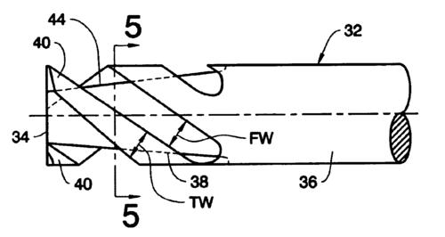
- Tooling Precision: Use high-stiffness tool holders (e.g., hydraulic or shrink-fit) to minimize tool runout (<0.002mm). Carbide or ceramic tools with sharp edges (rake angle 5–10°) reduce cutting forces, critical for thin-walled parts (0.5–2mm thickness) prone to deformation.
2. Process Optimization
Refined machining workflows directly reduce errors from setup, cutting, and environmental factors:
-
Rigorous Setup & Fixturing: Use precision vises or custom jigs with repeatability ≤0.002mm. For complex parts, 3D-printed fixtures (with ±0.01mm accuracy) ensure consistent clamping, avoiding distortion. Pre-machining datum calibration (via CMM) aligns the workpiece to the machine coordinate system within ±0.003mm.
-
Cutting Parameter Tuning:
- Low-Force Machining: For materials like titanium or aluminum, use high spindle speeds (15,000–30,000 RPM) and low feed rates (0.01–0.05mm/rev) to reduce radial forces, minimizing workpiece deflection by 30–50%.
- Chatter Suppression: Adjust spindle speed to avoid resonance frequencies (identified via vibration sensors). Damping tools (e.g., tuned mass dampers) reduce surface waviness from chatter, improving surface finish from Ra 1.6μm to Ra 0.4μm.
- Coolant & Lubrication: High-pressure coolant (70–100 bar) directed at the cutting zone removes chips and controls heat, preventing thermal expansion of the workpiece (critical for steel parts, where a 1°C temperature rise causes ~12μm/m expansion).
-
Multi-Stage Machining: Split processes into roughing, semi-finishing, and finishing. Roughing removes 80–90% of material with higher feeds to minimize cycle time; semi-finishing leaves 0.1–0.3mm stock to account for stress relief; finishing uses small tools (diameter 1–5mm) with slow feeds (0.005–0.02mm/rev) to hit tight tolerances.
3. Material Stability & Preparation
Material properties significantly impact precision, requiring strict control:
- Material Homogeneity: Use high-quality raw materials (e.g., aerospace-grade aluminum 7075, titanium Ti-6Al-4V) with uniform grain structure to avoid machining inconsistencies. Forged or annealed materials reduce internal stress, minimizing post-machining warpage (e.g., annealed steel parts warp <0.01mm/m vs. unannealed ones).
- Stress Relief: Prior to machining, perform thermo-mechanical aging (e.g., heating aluminum to 120°C for 24 hours) to release residual stresses from casting or rolling. This reduces dimensional changes after machining by 60–80%, critical for large parts (e.g., 1m-long structural beams).
- Thermal Expansion Management: Select materials with low coefficients of thermal expansion (CTE) for temperature-sensitive applications. Invar (Fe-Ni alloy) has a CTE of 1.2×10⁻⁶/°C (vs. steel’s 12×10⁻⁶/°C), ideal for precision molds or optical components.
4. Part Design & Complexity Adaptation
Design features influence achievable precision, requiring tailored strategies:
- Geometric Simplification: Avoid sharp corners (use radii ≥0.1mm) and deep, narrow slots (depth-to-width ratio <5:1) to reduce tool deflection. For example, a 0.5mm-wide slot with 3mm depth is harder to machine precisely than a 1mm-wide slot of the same depth.
- Thin-Wall Handling: For walls <1mm thick (e.g., aerospace brackets), use low-cutting-force tools (e.g., carbide end mills with 0° rake angle) and climb milling to minimize pushing forces. Support structures (e.g., temporary webs) during machining prevent warpage, removed in final steps.
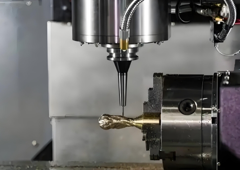
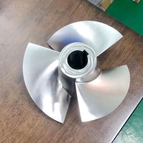
- Complex Surfaces: Use 5-axis machining for 3D contours (e.g., turbine blades, mold cavities). Continuous tool axis rotation maintains optimal cutting angles, reducing scallop height (the step between tool paths) to <0.005mm, improving surface finish.
5. Inspection & Quality Control
Stringent measurement ensures precision meets requirements:
- In-Process Inspection: Integrate probes (e.g., Renishaw OMP40) into CNC machines to measure critical dimensions during machining. For example, after roughing a bore, the probe checks diameter, adjusting finishing tool paths to correct ±0.003mm deviations.
- Post-Machining Metrology: Use high-precision CMMs (accuracy ±0.0005mm) or optical scanners (resolution 0.001mm) to verify features. For surface finish, profilometers measure Ra (target <0.05μm for optical parts) and Rz (peak-to-valley height) to ensure functional performance (e.g., seal mating surfaces).
- Statistical Process Control (SPC): For batch production, monitor key dimensions (e.g., hole position, thickness) across 50+ parts. SPC identifies trends (e.g., tool wear causing 0.001mm/day diameter increase), triggering tool changes or parameter adjustments to maintain consistency.
6. Industry-Specific Requirements & Scenarios
Precision needs vary by sector, dictating targeted approaches:
- Aerospace & Defense: Parts like engine nozzles or gyroscope housings require ±0.001mm tolerances. Machining uses ultra-stable CNCs (temperature-controlled to ±1°C) and diamond turning for optical-grade surfaces (Ra <0.02μm).
- Medical Devices: Surgical tools (e.g., laparoscopic forceps) need smooth edges (burr-free, Ra <0.1μm) to avoid tissue damage. Micro-CNC machines (spindle speed up to 100,000 RPM) machine 0.1mm-diameter features with ±0.0005mm accuracy.
- Precision Instruments: Watch components (e.g., gear teeth) demand tight pitch tolerances (±0.002mm). 5-axis machining with high-resolution encoders ensures gear profiles match CAD models exactly, reducing friction and improving longevity.
- Electronics: Semiconductor test sockets (contact pins <0.3mm diameter) require positional accuracy ±0.005mm. Machining uses non-magnetic tools and anti-vibration mounts to avoid interference with sensitive electronics.
In summary, improving CNC part precision is a holistic process, combining advanced equipment, material control, process refinement, and rigorous inspection. By addressing each stage—from raw material to final measurement—manufacturers achieve the tight tolerances and consistency critical for high-performance applications.